Biostar P4TSE P4TSE user's manual - Page 13
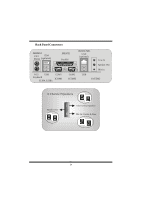
Clear CMOS Jumper: JCMOS1, Case Open Connector: JCL1, Serial ATA Connector: JSATA1/ JSATA2, AUDIO DJ
 |
View all Biostar P4TSE manuals
Add to My Manuals
Save this manual to your list of manuals |
Page 13 highlights
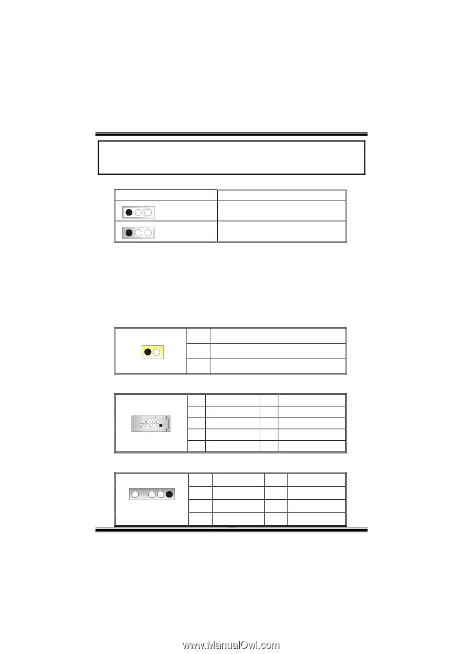
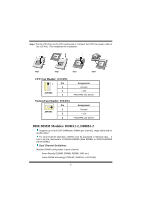
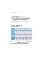
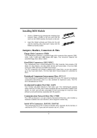
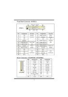
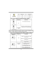
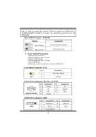
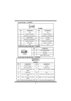
Note: In order to support this function "Power-on system via USB device", "JUSBV1/JUSBV2/ JUSBV3_4" jumper cap should be placed on pin 2-3 individually. Clear CMOS Jumper: JCMOS1 JCMOS1 Assignment 1 3 Pin 1-2 Close Normal Operation (default) 1 3 Pin 2-3 Close Clear CMOS Data ※ Clear CMOS Procedures: 1. Remove AC power line. 2. Set the jumper to "Pin 2-3 Close". 3. Wait for five seconds. 4. Set the jumper to "Pin 1-2 Close". 5. Power on the AC. 6. Reset your desired password or clear the CMOS data. Case Open Connector: JCL1 Pin 1 2 1 JCL1 2 Assignment Case Open Signal Ground Serial ATA Connector: JSATA1/ JSATA2 Pin Assignment Pin 65 3 2 1 Ground 2 3 TX- 4 741 5 RX- 6 JSATA1/ JSATA2 7 Ground Assignment TX+ Ground RX+ AUDIO DJ Connector: JDJ1 Pin Assignment Pin 5 11 SMBDATA 2 JDJ1 3 INT_B 4 5 ATX_PWROK Assignment SMBCLK KEY 11
-
 1
1 -
2
-
3
-
4
-
5
-
6
-
7
-
 8
8 -
 9
9 -
 10
10 -
 11
11 -
 12
12 -
 13
13 -
 14
14 -
 15
15 -
 16
16 -
 17
17 -
 18
18 -
19
-
20
-
21
-
22
-
23
-
24
-
25
-
26
-
27
-
28
-
29
-
30
-
31
-
32
-
33
-
34
-
35
-
36
-
37
-
38
-
39
-
40
 |
 |