Biostar P4TSE P4TSE user's manual - Page 7
Package contents, How to set up Jumper, CPU Installation - drivers
 |
View all Biostar P4TSE manuals
Add to My Manuals
Save this manual to your list of manuals |
Page 7 highlights
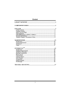
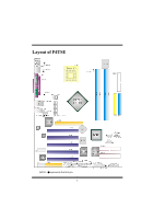
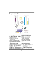
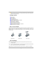
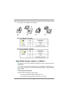
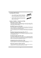
Offers the highest performance for Windows 98 SE, Windows 2000, Windows Me, Windows XP, SCO UNIX etc. Package contents HDD Cable X 1 FDD Cable X 1 User's Manual X 1 Fully Setup Driver CD X 1 StudioFun! Application CD X 1 (optional) USB 2.0 Cable X1 (optional) S/PDIF Cable X 1 (optional) Rear I/O Panel for ATX Case X 1 Serial ATA Cable X 1 (optional) Serial ATA Power Switch Cable X 1 (optional) IEEE 1394 Cable X 1 (optional) How to set up Jumper The illustration shows to how set up jumper. When the Jumper cap is placed on pins, the jumper is "close". IF no jumper cap is placed on the pins, the jumper is "open". The illustration shows a 3-pin jumper whose pin1and 2 are "close" when jumper cap is placed on these 2 pins. Jumper open Jumper close Pin1-2 close CPU Installation Step1: Pull the lever sideways away from the socket and then raise the lever up to a 90-degree angle. Step2: Look for the white dot/cut edge. The white dot/cut edge should point wards the lever pivot. The CPU will fit only in the correct orientation. Step3: Hold the CPU down firmly, and then close the lever to complete the installation. 5
-
 1
1 -
 2
2 -
 3
3 -
 4
4 -
 5
5 -
 6
6 -
 7
7 -
 8
8 -
 9
9 -
 10
10 -
 11
11 -
 12
12 -
13
-
14
-
15
-
16
-
17
-
18
-
19
-
20
-
21
-
22
-
23
-
24
-
25
-
26
-
27
-
28
-
29
-
30
-
31
-
32
-
33
-
34
-
35
-
36
-
37
-
38
-
39
-
40
 |
 |