Biostar TPOWER N750 Setup Manual - Page 21
On-Board Buttons, JSPDIF_OUT1/JSPDIF_OUT2: Digital Audio-out Connectors, JSPDIF_IN1: Digital Audio-
 |
View all Biostar TPOWER N750 manuals
Add to My Manuals
Save this manual to your list of manuals |
Page 21 highlights
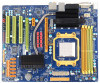
On-Board Buttons There are 2 on-board buttons. TPower N750 PWRSW1 RSTSW1 PWRSW1: This is an on-board Power Switch button. RSTSW1: This is an on-board Reset button. JSPDIF_OUT1/JSPDIF_OUT2: Digital Audio-out Connectors This connector allows user to connect the PCI bracket SPDIF output header. JSP DIF _OUT1 JSPDI F_ O UT 2 13 Pin Assignment 1 +5V 2 SPDIF_OUT 3 Ground JSPDIF_IN1: Digital Audio-in Connector This connector allows user to connect the PCI bracket SPDIF input header. 13 Pin Assignment 1 +5V 2 SPDIF_IN 3 Ground 19
-
 1
1 -
2
-
3
-
4
-
5
-
6
-
7
-
8
-
9
-
10
-
11
-
12
-
13
-
14
-
15
-
 16
16 -
 17
17 -
 18
18 -
 19
19 -
 20
20 -
 21
21 -
 22
22 -
 23
23 -
 24
24 -
 25
25 -
 26
26 -
27
-
28
-
29
-
30
-
31
-
32
-
33
-
34
-
35
-
36
-
37
-
38
-
39
-
40
-
41
-
42
-
43
-
44
-
45
-
46
-
47
-
48
-
49
-
50
-
51
-
52
-
53
-
54
-
55
-
56
-
57
-
58
-
59
-
60
-
61
-
62
-
63
-
64
-
65
-
66
-
67
-
68
-
69
 |
 |

TPower N750
19
On-Board Buttons
There are 2 on-board buttons.
PWRSW1
RSTSW1
PWRSW1:
This is an on-board Power Switch button.
RSTSW1:
This is an on-board Reset button.
JSPDIF_OUT1/JSPDIF_OUT2: Digital Audio-out Connectors
This connector allows user to connect the PCI bracket SPDIF output header.
Pin
Assignment
1
+5V
2
SPDIF_OUT
1
3
JSPDIF_OUT1
JSPDIF_OUT2
3
Ground
JSPDIF_IN1: Digital Audio-in Connector
This connector allows user to connect the PCI bracket SPDIF input header.
Pin
Assignment
1
+5V
2
SPDIF_IN
1
3
3
Ground