Bosch B18ID80NRP Installation Instructions
Bosch B18ID80NRP Manual
 |
View all Bosch B18ID80NRP manuals
Add to My Manuals
Save this manual to your list of manuals |
Bosch B18ID80NRP manual content summary:
- Bosch B18ID80NRP | Installation Instructions - Page 1
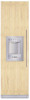
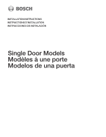
INSTALLATION INSTRUCTIONS INSTRUCTIONS D'INSTALLATION INSTRUCCIONES DE INSTALACIÓN Single Door Models Modèles à une porte Modelos de una puerta - Bosch B18ID80NRP | Installation Instructions - Page 2
2 - Bosch B18ID80NRP | Installation Instructions - Page 3
instruction 8 Connecting the water 8 Installation dimensions 9 Single installation 9 SideĆbyĆSide installation 10 Water connection 11 Appliance dimensions 12 1. 18" Appliance (Freezer/Freezer with Ice and Water dispenser 12 2. 18" Appliance (Wine unit 13 3. 24" Appliance (Refrigerator - Bosch B18ID80NRP | Installation Instructions - Page 4
Installation instructions 18 1. Checking the installation cavity 18 2.. Transport of the appliance 18 3. Removing the packaging 19 4. Preparing the appliance 19 5. Changing over the door hinges 20 6. Preparing the installation cavity 22 7. Attaching an alternative antiĆtip device 24 8. - Bosch B18ID80NRP | Installation Instructions - Page 5
the possibility of tipping forward. AntiĆtip protection is required. Keep doors closed until the appliance is completely installed and secured per installation instructions. Due to the weight and size of this appliance, and to reduce the risk of personal injury or damage to the product ć TWO PEOPLE - Bosch B18ID80NRP | Installation Instructions - Page 6
is visible, a side panel must be used. The side panel must be connected firmly to the wall, the floor and overhead furniture/fixtures before the appliance is placed in the cavity. The dimensions of the side panel are taken from the opposite cavity wall. During installation ensure that the cavity is - Bosch B18ID80NRP | Installation Instructions - Page 7
dimensions of the installation cavity for a troubleĆfree installation of the appliance and for the subsequent general view of 18" Wine unit 24" approx. 550 lbs / 245 kg approx. 694 lbs / 310 kg (* without Water Dispenser) To ensure that the appliance is installed securely and functions properly, - Bosch B18ID80NRP | Installation Instructions - Page 8
: Appliance Refrigerator24" Refrigerator 30" Freezer 18" (incl. IceMaker) Freezer 24" appliance to plastic plumbing lines, gas lines or water pipes. Grounding instruction This appliance appliance checked by a qualified electrician or service technician if you are in doubt as to whether the appliance - Bosch B18ID80NRP | Installation Instructions - Page 9
of the power connection D Opening depth of niche, depending on kitchen design (see DESIGN GUIDE) D = 24" (610 mm) minimum NOTE: Cavity must be suare. Side wall of the cavity must be flush. Appliance 18" 24" 30" X 18" (457 mm) 24 (610 mm) 30" (762 mm) Y 9" (229 mm) 12" (305 mm) 15" (381 mm - Bosch B18ID80NRP | Installation Instructions - Page 10
the cavity results from the addition of the cavity widths indicated for the two appliances. Example: Freezer 18" / Refrigerator 30" Legend: A Area for installation of niche, depending on kitchen design (see DESIGN GUIDE) D = 24" (610 mm) minimum NOTE: Cavity must be suare. Side wall of the cavity - Bosch B18ID80NRP | Installation Instructions - Page 11
Water connection The supply pipe can be located a) at the side on the right, b) at the side on the left or c) underneath. 11 - Bosch B18ID80NRP | Installation Instructions - Page 12
dimensions7. 1. 18" Appliance (Freezer/Freezer with Ice and Water dispenser) e) e) Front view (without door panel) Legend: a) Adjustment in levelling legs +13/8" (35 mm) / : One design of the wooden panel displayed. For further information about the different styles check the DESIGN GUIDE. - Bosch B18ID80NRP | Installation Instructions - Page 13
2. 18" Appliance (Wine unit) e) e) Front view (without door panel) Legend: a) Adjustment in levelling legs +13/8" (35 mm) / -1/2" (13 mm). b) Dimensions may dimensions Note: One design of the wooden panel displayed. For further information about the different styles check the DESIGN GUIDE. 13 - Bosch B18ID80NRP | Installation Instructions - Page 14
3. 24" Appliance (Refrigerator/Freezer/Freezer with Ice and Water dispenser) e) e) Front view (without door panel) Legend: a) Adjustment in levelling legs +13/8" (35 mm) 14 Note: One design of the wooden panel displayed. For further information about the different styles check the DESIGN GUIDE. - Bosch B18ID80NRP | Installation Instructions - Page 15
4. 24" Appliance (Wine unit) e) e) Front view (without door panel) Legend: a) Adjustment in levelling legs +13/8" (35 mm) / -1/2" (13 mm). b) Dimensions may dimensions Note: One design of the wooden panel displayed. For further information about the different styles check the DESIGN GUIDE. 15 - Bosch B18ID80NRP | Installation Instructions - Page 16
5. 30" Appliance (Refrigerator/Freezer/Freezer with Ice and Water dispenser) e) e) Front view (without door panel) Legend: a) Adjustment in levelling legs +13/8" (35 mm) 16 Note: One design of the wooden panel displayed. For further information about the different styles check the DESIGN GUIDE. - Bosch B18ID80NRP | Installation Instructions - Page 17
Required accessories and tools 1. Supplied accessories - Installation instructions - Operating instructions - Installation kit 2. Optional accessories8. Basic Combination SideĆbyĆSide Sealing kit For permanent connection of two individual appliances, e. g. Freezer next to Refrigerator. Extreme - Bosch B18ID80NRP | Installation Instructions - Page 18
the water connection. (only for appliances with ice maker) Also follow the instructions in the section on Connecting the water" on page 8. q Check attachment of the adjacent furniture/fixtures. All furniture parts in the vicinity of the appliance must be connected securely to the wall. q Check that - Bosch B18ID80NRP | Installation Instructions - Page 19
which attach the furniture fronts. To do this, loosen the fastening screws and remove the stop parts. i Store the stop parts in suitable receptacles, otherwise they may get lost. q Move the appliance with a hand truck securely. q Remove transportation packaging: - Remove the cartoon. Use the cutter - Bosch B18ID80NRP | Installation Instructions - Page 20
. q Unscrew the door. q Release the spring on the hinge. Loosen the screw from I to 0. q Remove the hinges. q Remove the hinge box covers. 20 q Remove the parts of grill. i It will used new - Bosch B18ID80NRP | Installation Instructions - Page 21
q Change over the hinge angle. q Fix the hinges on the appliance. Change the hinges crosswise! q Fit the plastic part of the grill. q Mount the grill completely. q Fix the door. q Change over the fixation parts on the door. q Span the spring on the hinge. Tighten the screw from 0 to I. 21 - Bosch B18ID80NRP | Installation Instructions - Page 22
of injury and damage! q Change the attachment plates crosswise. 22 (609,6-647,7) q If the installation cavity is deeper than the appliance, place a solid wooden beam behind the antiĆtipĆbrackets and attach securely to the base or the wall. The length of the wooden beam is equal to the width of the - Bosch B18ID80NRP | Installation Instructions - Page 23
penetrate through the flooring and into the wall plate a minimum of 3/4" (19 mm). q Attach the antiĆtipĆbracket completely. Be sure screws hold tight. q Manually insert the screw into the wall plug until the screw begins to resist. q Knock the wall plug and screw into the hole until the screw - Bosch B18ID80NRP | Installation Instructions - Page 24
brackets cannot be attached securely, an alternative antiĆtip device can be attached. However, ensure that there is no play between the appliance and the antiĆtip pipe to the shutĆoff valve according to the instructions supplied by the manufacturer of the ice maker installation attached securely. 24 - Bosch B18ID80NRP | Installation Instructions - Page 25
Attaching the edge protection 10.SideĆbyĆSide installation i If a sideĆbyĆside installation is intended, now connect the two appliances together. See the Installation Manual for the SideĆbyĆSide kits. q To protect the corners of the installation cavity, attach the supplied protective brackets with - Bosch B18ID80NRP | Installation Instructions - Page 26
with the antiĆtip brackets. 12. Installing and aligning the appliance q Remove edge protection. q Align the appliance with the furniture fronts. Place markingĆout level over the installation aid parts on the door. i The installation aid parts on the door have been designed for the following total - Bosch B18ID80NRP | Installation Instructions - Page 27
to point 6 of this installation manual, rotate the appliance all the way towards the wooden beam. 13. Attaching the appliance to the top of the cavity q Unscrew the heightĆadjustable feet until the mark on the base has reached the indicated guide dimension - Bosch B18ID80NRP | Installation Instructions - Page 28
i When connecting the water pipe to the solenoid valve of the appliance, follow the instructions supplied by the manufacturer of the ice maker installation kit enclosed with the installation manual. d CAUTION d When bending the water pipe, do not kink it, otherwise there is a risk of leaks - Bosch B18ID80NRP | Installation Instructions - Page 29
overturn! q Open the shutĆoff valve and main water tap. Check the connection on the shutĆoff valve and on the appliance for leaks. q Attach the base panel to the appliance. q Remove the protective film from the adhesive pads on the Velcro. q Fit the toe kick panel to the base panel and - Bosch B18ID80NRP | Installation Instructions - Page 30
are screw holes in the base panel near the Velcro. q Pull out the brackets by the measured amount Y. q Screw the brackets tightly. 17. Commissioning the Appliance To guarantee the accuracy of the following working steps and thus the appearance of the overall kitchen front later on, the - Bosch B18ID80NRP | Installation Instructions - Page 31
/ 17 kg 24" 50 lbs / 23 kg 30" 64 lbs / 29 kg The furniture fronts are attached to the appliance door by means of fitting parts on the appliance. These fitting parts allow the furniture door to be adjusted precisely and attached securely to the appliance. Function of different parts: 1. Double - Bosch B18ID80NRP | Installation Instructions - Page 32
to ensure that the gap width is as precise as possible. Recommendations: 18" Appliance 22 lbs / 10 kg 24" Appliance 33 lbs / 15 kg 30" Appliance 44 lbs / 20 kg q Unscrew the installation support part from the appliance door. i Using the positioning aid, set both longitudinal sides of the furniture - Bosch B18ID80NRP | Installation Instructions - Page 33
be inserted under each double threaded bolt. q Align the furniture door with the double threaded bolts (Torx screwdriver). * Wine unit - The adjusting rail features a variety of holes for the many different design options of furniture doors. Always screw into the best loadĆbearing material of the - Bosch B18ID80NRP | Installation Instructions - Page 34
do this, insert the bracket directly behind the furniture handle into the associated fixing plate. Slide the bracket onto the screw on the appliance door and tighten. Align the furniture door with the double threaded bolts (Torx screwdriver). Then loosen the bracket screw again. After erecting the - Bosch B18ID80NRP | Installation Instructions - Page 35
nuts on the adjusting rail. This will fix the side alignment of the door. q Attach the bracket: - Lift the furniture door slightly away from the appliance door. - Push the side bracket (1.) on the left and right over the screws. - Insert the side bracket (2.) on the left and right into the fixing - Bosch B18ID80NRP | Installation Instructions - Page 36
24. Attaching the finger guard i The number of lower brackets depends on the width be situated exactly at the height of the brackets! q Insert the finger guard into the gap between the appliance and adjacent furniture (1.). q Clamp the finger guard under the brackets (2.). q Push the cap onto the - Bosch B18ID80NRP | Installation Instructions - Page 37
of the cover strip is shorter on the side on which the finger guard has been attached. q Attach the light switch cover. i The cover for 24", 30" and 36" appliances can be screwed to the door. 37 - Bosch B18ID80NRP | Installation Instructions - Page 38
to be aligned parallel to the furniture door in order to obtain an optimum overall appearance. q Remove covers. q Loosen screws on the 4 clamps. A Appliance B Furniture q Screw on the brackets (side) for holding the cover strip. 38 q Insert flat screwdriver into one of the 4 slots and push the - Bosch B18ID80NRP | Installation Instructions - Page 39
q ReĆattach covers. 27. Attaching the cover frame and the shelf (for freezer unit with iceĆwater dispenser only) q Insert shelf. 28. Attaching the cover strips (for wine storage cupboard only) Note: For 3/4" / 19 mm thick furniture doors: q Slide cover frame onto the iceĆwater dispenser and press - Bosch B18ID80NRP | Installation Instructions - Page 40
in the diagram. q Slowly close the door. Check whether the air separator collides with parts of the ventilation grille. If required, shorten the longitudinal side of the air separator by approx. 6mm. For appliances with iceĆwater dispenser: q The air separator must be cut out in the area of - Bosch B18ID80NRP | Installation Instructions - Page 41
30. Adjusting the door opening angle Depending on the installation situation, it may be necessary to adjust the door opening angle. A door opening angle of 115° has been set at the factory. To adjust the door opening angle to 90°: q Open door to 90°. 31. Changing the door spring To adjust the door - Bosch B18ID80NRP | Installation Instructions - Page 42
42 - Bosch B18ID80NRP | Installation Instructions - Page 43
49 Procédure additionnelle de mise à la terre 49 Instructions de raccordement à la terre 49 Raccordement de l'eau 49 (Cave à vin 54 3. Appareil de 24" (Réfrigérateur/Congelateur/Congélateur avec une distributeur de glaçons et d'eau) . 55 4. Appareil de 24" (Cave à vin 56 5. Appareil de - Bosch B18ID80NRP | Installation Instructions - Page 44
Instructions d'installation 59 1. l'appareil 69 16. Fixation du bandeau de socle 70 17. Mise en service de l'appareil 71 18. Préparation des portes de meubles 71 19. de meuble 75 23. Raccourcir le bandeau protègeĆdoigts 76 24. Fixation du bandeau protègeĆdoigts 77 25. Fixation des couvercles - Bosch B18ID80NRP | Installation Instructions - Page 45
éteinte avant de nettoyer ou d'effectuer des réparations. Les réparations sont réservées à un technicien qualifié du service aprèsĆvente. Les présentes instructions d'installation sont destinées à être utilisées par des installateurs qualifiés. Tous les raccordements de l'eau, de l'électricit - Bosch B18ID80NRP | Installation Instructions - Page 46
assortie d'un danger de mort ou de blessures graves si vous ne respectez pas son contenu. d PRUDENCE d PRUDENCE ć Cette mention précède une instruction assortie d'un risque de blessures légères ou de dégâts si vous ne respectez pas son contenu. i Ce symbole sert à attirer votre attention sur - Bosch B18ID80NRP | Installation Instructions - Page 47
vide, reportezĆvous au tableau suivant : Réfrigérateur de 24" Réfrigérateur de 30" env. 310 lbs/140 kg env. 350 lbs/158 kg Congélateur 300 lbs/135 kg* env. 335 lbs/150 kg* Cave à vin 18" Cave à vin 24" (* sans distributeur d'eau) env. 300 lbs/135 kg env. 364 lbs/160 kg Local d' - Bosch B18ID80NRP | Installation Instructions - Page 48
élateur 30" env. 560 lbs/250 kg* env. 780 lbs/350 kg* env. 950 lbs/425 kg* Cave à vin 18" Cave à vin 24" env. 550 lbs/245 kg env. 694 lbs/310 kg (* sans distributeur d'eau) Pour être sûr que l'appareil a été installé de façon sûre et qu'il - Bosch B18ID80NRP | Installation Instructions - Page 49
un fusible/disjoncteur supportant un ampérage 24" Réfrigérateur 30" Congélateur 18" (y compris distributeur de glaçons) Congélateur 24 exiger un raccordement à part à la terre. de gaz ou conduites d'eau. Instructions de raccordement à la terre Cet ou un technicien du service aprèsĆvente. Raccordement - Bosch B18ID80NRP | Installation Instructions - Page 50
la zone où installer le raccordement de l'électricité D profondeur d'ouverture de la cavité, ceci dépendant de la configuration de la cuisine (Voir le GUIDE DE CONCEPTION) D = 24" (610 mm) minimum REMARQUE : La cavité doit être carrée. La paroi latérale de la cavité doit se trouver dans l'alignement - Bosch B18ID80NRP | Installation Instructions - Page 51
ésente la zone où installer le raccordement de l'électricité D Profondeur de la cavité, ceci dépendant de la configuration de la cuisine (Voir le GUIDE DE CONCEPTION) D = 24" (610 mm) minimum REMARQUE : La cavité doit être carrée. La paroi latérale de la cavité doit se trouver dans l'alignement. 51 - Bosch B18ID80NRP | Installation Instructions - Page 52
Installation côte à côte Il est possible de placer la conduite d'alimentation a) sur le côté droit (a), b) sur le côté gauche (b) ou c) en dessous (c). 52 - Bosch B18ID80NRP | Installation Instructions - Page 53
ne représentent qu'un style de panneau en bois. Pour obtenir des informations avancées sur les différents styles, veuillez vous reporter au GUIDE DE CONCEPTION. 53 - Bosch B18ID80NRP | Installation Instructions - Page 54
ne représentent qu'un style de panneau en bois. Pour obtenir des informations avancées sur les différents styles, veuillez vous reporter au GUIDE DE CONCEPTION. 54 - Bosch B18ID80NRP | Installation Instructions - Page 55
3. Appareil de 24" (Réfrigérateur/Congelateur/Congélateur avec une distributeur de glaçons et d'eau) e) e) Vue de face (sans le panneau de porte) Légende style de panneau en bois. Pour obtenir des informations avancées sur les différents styles, veuillez vous reporter au GUIDE DE CONCEPTION. 55 - Bosch B18ID80NRP | Installation Instructions - Page 56
4. Appareil de 24" (Cave à vin) e) e) Vue de face (sans le panneau de porte) Légende : a) Ajustage des pieds de nivellement entre + 1 3/8" (35 mm) et ½" (13 style de panneau en bois. Pour obtenir des informations avancées sur les différents styles, veuillez vous reporter au GUIDE DE CONCEPTION. - Bosch B18ID80NRP | Installation Instructions - Page 57
ne représentent qu'un style de panneau en bois. Pour obtenir des informations avancées sur les différents styles, veuillez vous reporter au GUIDE DE CONCEPTION. 57 - Bosch B18ID80NRP | Installation Instructions - Page 58
requis 1. Accessoires fournis - Instructions d'installation - Instructions d'utilisation - Kit d'installation Outils - Visseuse sans cordon T20 - Tournevis Torx T20 (empreinte cruciforme) - Embout Torx T20 + support magnétique - Clé à pipe 5/16" (8 mm)I pour écrou hexagonal - Forets à bois - Bosch B18ID80NRP | Installation Instructions - Page 59
installation sûre et sans incident. q Vérifiez le sol. Suivez les instructions figurant à la page 6 dans la section «Lieu d'installation». q Vérifiez via le Redressement dos de l'appareil via la paroi arrière de l'appareil 18" / 457 mm 24" / 610 mm 30" / 762 mm 36" / 914 mm 86" / 2185 mm 86" - Bosch B18ID80NRP | Installation Instructions - Page 60
3. Enlèvement de l'emballage d AVERTISSEMENT d - L'appareil risque de se renverser pendant son déballage. - L'appareil est très lourd. - Lorsque vous ouvrez la porte de l'appareil, ce dernier risque de basculer en avant. Soyez prudent, sinon les personnes qui vous aident risquent de se blesser et l' - Bosch B18ID80NRP | Installation Instructions - Page 61
q Détendez le ressort sur la charnière. Desserrez la vis en l'amenant de I à 0. q Retirez les charnières. q Retirez le couvercle du boîtier à charnière. q Retirez les pièces de la grille. q Dévissez la porte. 61 - Bosch B18ID80NRP | Installation Instructions - Page 62
i ServezĆvous de pièces neuves. q Permutez l'angle de la charnière. q Fixez les charnières sur l'appareil. Permutez les charnières selon un ordre croisé ! q Adaptez la pièce en plastique de la grille. q Montez au complet les pièces de la grille. q Fixez la porte. q Permutez les pièces de - Bosch B18ID80NRP | Installation Instructions - Page 63
(609,6-647,7) q Refixez le couvercle de la boîte à charnière. q Permutez les plaques de fixation selon un ordre croisé. 6. Préparation de la cavité d'installation i Il faut 2 brides antiĆrenversement pour chaque appareil ou combinaison d'appareils (côte à côte). q Déterminez les points de fixation - Bosch B18ID80NRP | Installation Instructions - Page 64
Application sur plancher en bois Utilisez les vis à bois (5x60 mm et 4x15 mm) fournies avec l'appareil. q Percez des trous de guidage : De 1/8" (3 mm) pour les vis à bois faisant 5x60 mm De 5/64" (2 mm) pour les vis à bois faisant 4x15 mm AssurezĆvous que les vis traversent bien le plancher et pénè - Bosch B18ID80NRP | Installation Instructions - Page 65
cher que l'eau, en fuyant, ne provoque des dégâts. q Branchez la conduite de raccordement contre la vanne de fermeture en respectant les instructions fournies par le fabricant du kit destiné à l'installation du distributeur de glaçons. q Installez la conduite de raccordement. Respectez toujours les - Bosch B18ID80NRP | Installation Instructions - Page 66
9. Fixation du protègeĆbordures q Pour protéger les angles de la cavité, fixez les cornières de protection dans ces angles à l'aide de ruban adhésif. 10. Installation côte à côte i Si vous prévoyez une installation côte à côte, il faut relier maintenant les deux appareil l'un avec l'autre. Veuillez - Bosch B18ID80NRP | Installation Instructions - Page 67
1¼" (32 mm) auĆdessus du sol. q Dévissez les pieds réglables en hauteur jusqu'à ce que la marque sur la base/le sol a atteint la dimension guide indiquée (1¼"/32 mm). i Il est très important de respecter cette dimension pour pouvoir ensuite aligner les façades des meubles. q Alignez les façades des - Bosch B18ID80NRP | Installation Instructions - Page 68
i Remarque: - Ne voilez pas ni ne poussez pas l'appareil de force dans la cavité ! Lorsque vous dévissez les pieds réglables en hauteur, procédez graduellement : alternez en permanence entre les côtés gauche et droit, gauche et droit, etc. - Si vous délestez l'arrière de l'appareil, l'ajustage de - Bosch B18ID80NRP | Installation Instructions - Page 69
adjacents (uniquement dans le cas d'un appareil individuel) 15. Raccordement de l'eau à l'appareil i Lorsque vous raccordez la conduite d'eau à l'électrovanne de l'appareil, respectez les instructions fournies par le fabricant du kit servant à installer le distributeur de glaçons ; ces - Bosch B18ID80NRP | Installation Instructions - Page 70
16. Fixation du bandeau de socle d PRUDENCE d La hauteur maximale du bandeau de socle est de 4" depuis la surface du plancher. Ne recouvrez pas les ouïes de ventilation que comporte le panneau de base. Risque d'endommager l'appareil. q Si nécessaire, réduisez le bandeau de socle à la longueur - Bosch B18ID80NRP | Installation Instructions - Page 71
base, à proximité de la bande Velcro. 17. Mise en service de l'appareil Pour garantir la précision des étapes de constitutif de la porte, le mieux capable de supporter la charge. - Conservez les accessoires d'aide au les valeurs suivantes : 18" 37 lbs/17 kg 24" 50 lbs/23 kg 30" 64 lbs/29 kg - Bosch B18ID80NRP | Installation Instructions - Page 72
tallique contre leur dos. Ce bandeau est en vente auprès du service aprèsĆvente en tant qu'accessoire en option. Voir la section du matériau de porte la mieux en mesure de supporter la charge. Conservez les accessoires d'aide au positionnement, vous 24" 33 lbs/15 kg Appareil de 30" 44 lbs/20 kg 72 - Bosch B18ID80NRP | Installation Instructions - Page 73
d'ajustage constitue le moyen le plus important pour ajuster la façade du meuble. q De la porte de l'appareil, dévissez la pièce support d'installation. i Conservez les accessoires d'aide au positionnement, vous en aurez encore besoin dans la suite du montage. q Marquez cette distance X au dos de - Bosch B18ID80NRP | Installation Instructions - Page 74
és à différentes options de configuration des portes de meuble. Vissez toujours dans le matériau de la porte de meuble le mieux en mesure de supporter la charge. 21. Fixation et alignement de la porte de meuble i Les boulons à double filetage sont chargés d'ajuster la façade du meuble en hauteur - Bosch B18ID80NRP | Installation Instructions - Page 75
q Alignez la porte du meuble et contrôlez ce faisant la constance de l'interstice sur tout le périmètre. Si nécessaire, déplacez le rail d'ajustage vers la gauche ou la droite. q Vissez les plaques de fixation (10x) 22. Fixation de la porte de meuble i Maintenant, fixez les poignées du meuble. - Bosch B18ID80NRP | Installation Instructions - Page 76
1. Desserrez la vis. 2. Vérifiez la position latérale de la porte. 3. Vissez la vis à bois. 4. Serrez la vis. 5. Fixez le couvercle sur les brides. q Refermez la porte et vérifiez l'alignement latéral. Corrigez en tapant légèrement avec la main sur le bord de la porte ouverte du meuble. q Serrez - Bosch B18ID80NRP | Installation Instructions - Page 77
contre le bandeau protègeĆdoigts. q A l'aide d'un couteau et d'une règle en acier, raccourcissez le bandeau protègeĆdoigts jusqu'à la longueur requise. 24. Fixation du bandeau protègeĆdoigts q Poussez la coiffe sur la bride et vissez à fond. q Fixez le bandeau protègeĆdoigts sous la charnière - Bosch B18ID80NRP | Installation Instructions - Page 78
sur lequel le bandeau protègeĆdoigts a été fixé. q Fixez le couvercle de l'interrupteur d'éclairage. i Vous pouvez visser le couvercle destiné aux appareils de 24", 30" et 36" contre la porte. Installation côte à côte uniquement: q Placez les bandes couvercles contre la porte. q Insérez la bande - Bosch B18ID80NRP | Installation Instructions - Page 79
Appareils individuels uniquement: B A 26. Alignement du distributeur de glaçons et d'eau (seulement pour unité de congélation avec distriĆ buteur de glaçons et d'eau) Il est possible d'aligner en profondeur le distributeur de glaçons et d'eau dans la découpe ménagée dans la porte du meuble. Ceci - Bosch B18ID80NRP | Installation Instructions - Page 80
27. Fixation du cadre enjoliveur et de la tablette (seulement sur unité de congélation avec distributeur de glaçons et d'eau) 28. Fixation des baguettes couvreĆjoint (seulement pour la cave à vin) Remarque : Portes de meuble faisant 3/4" / 19 mm d'épaisseur: q Enfoncez le cadre enjoliveur sur le - Bosch B18ID80NRP | Installation Instructions - Page 81
q Enfoncez les baguettes couvreĆjoint dans la cavité située entre la porte du meuble et le bandeau en verre 29. Montage du séparateur d'air Vissez le séparateur d'air contre la porte du meuble afin de séparer l'air entrant et l'air sortant. q Fermez la porte lentement. Contrôlez si le séparateur d' - Bosch B18ID80NRP | Installation Instructions - Page 82
31. Changement du ressort de porte Pour ajuster le ressort de porte : q A l'aide d'un tournevis à empreinte cruciforme, tournez la vis d'ajustage I = Plus forte tension possible du ressort 0 = Pas de tension ressort 82 - Bosch B18ID80NRP | Installation Instructions - Page 83
con dispensador de agua 94 4. Electrodoméstico de 24" (Conservador de vinos 95 5. Electrodoméstico de 30" (Refrigerador/Congelador/Congelador con dispensador de agua 96 Accesorios y herramientas necesarias 97 1. Accesorios que forman parte del volumen de entrega 97 2. Accesorios opcionales 97 - Bosch B18ID80NRP | Installation Instructions - Page 84
ón del electrodoméstico 106 13. Sujetando el electrodoméstico a la parte superior de la cavidad 107 14. Sujeción del electrodoméstico individual la puerta del mueble 114 23. Corte de la protección para los dedos 115 24. Montaje de la protección para los dedos 116 25. Montaje de las cubiertas - Bosch B18ID80NRP | Installation Instructions - Page 85
C22.1 - última edición prescripciones municipales y/o locales. e ADVERTENCIA La parte superior de este electrodoméstico es más pesada que la de abajo, por instalación inadecuada no esta cubiertos por la garantía. Consulte el manual del usuario por la información concerniente a la garantía. e - Bosch B18ID80NRP | Installation Instructions - Page 86
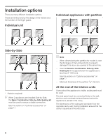
Opciones de instalación Existen diversas opciones de instalación. Están limitadas exclusivamente por el diseño de la cocina y la función de la protección para los dedos. Unidad individual Electrodomésticos individuales con separación 1. 2. SideĆbyĆSide (Lado a lado) * * * ¡Separación - Bosch B18ID80NRP | Installation Instructions - Page 87
kg* Conservador de vinos 18" aprox. 300 lbs / 135 kg Conservador de vinos 24" aprox. 360 lbs / 160 kg (* sin expendedor de agua) i Las paredes kg* Conservador de vinos 18" aprox. 550 lbs / 245 kg Conservador de vinos 24" aprox. 694 lbs / 310 kg (* sin expendedor de agua) Para asegurar que - Bosch B18ID80NRP | Installation Instructions - Page 88
soporte correspondiente. Rogamos tener en cuenta a tal fin, la tabla siguiente: Electrodoméstico Refrigerador de 24" Refrigerador de 30" Congelador de 18" (incl. fabricador de hielo) Congelador de 24" (incl. fabricador de hielo) Congelador de 30" (incl. fabricador de hielo) Carga simultánea máxima - Bosch B18ID80NRP | Installation Instructions - Page 89
ón de agua B Zona para la conexión a la red de potencia D Altura de la abertura, según el diseño de la cocina (consultar la GUÍA DE DIESEÑO) D = 24" (610 mm) como mínimo Nota: La cavidad debe estar a escuadra. La pared lateral de la cavidad debe ser plana. Electrodoméstico 18 - Bosch B18ID80NRP | Installation Instructions - Page 90
agua B Zona para la conexión a la red de potencia 90 D Altura de la abertura, según el diseño de la cocina (consultar la GUÍA DE DIESEÑO) D = 24" (610 mm) como mínimo Nota: La cavidad debe estar a escuadra. La pared lateral de la cavidad debe ser plana. - Bosch B18ID80NRP | Installation Instructions - Page 91
Conexión del agua11. La tubería de alimentación puede ubicarse a) al costado derecho (a), b) al costado izquierdo (b), o c) debajo (c). 91 - Bosch B18ID80NRP | Installation Instructions - Page 92
e) Medidas de la unidad Nota: Se visualiza un diseño de panel de madera. Por más información respecto de diferentes estilos, consulte la guía de diseño (DESIGN GUIDE). - Bosch B18ID80NRP | Installation Instructions - Page 93
. e) Medidas de la unidad Nota: Se visualiza un diseño de panel de madera. Por más información respecto de diferentes estilos, consulte la guía de diseño (DESIGN GUIDE). 93 - Bosch B18ID80NRP | Installation Instructions - Page 94
3. Electrodoméstico de 24" (Refrigerador/Congelador/Congelador con dispensador de agua) e) e) Vista frontal (sin la puerta) Leyenda a) Ajuste con patas niveladoras + 13/8" (35 mm ño de panel de madera. Por más información respecto de diferentes estilos, consulte la guía de diseño (DESING GUIDE). - Bosch B18ID80NRP | Installation Instructions - Page 95
4. Electrodoméstico de 24" (Conservador de vinos) e) e) Vista frontal (sin la puerta) Leyenda: a) Ajuste con patas niveladoras + 13/8" (35 mm)/- 1/2" (13 mm). b) un diseño de panel de madera. Por más información respecto de diferentes estilos, consulte la guía de diseño (DESIGN GUIDE). 95 - Bosch B18ID80NRP | Installation Instructions - Page 96
de la unidad 96 Nota: Se visualiza un diseño de panel de madera. Por más información respecto de diferentes estilos, consulte la guía de diseño (DESING GUIDE). - Bosch B18ID80NRP | Installation Instructions - Page 97
y calentamiento) Si el espacio entre los electrodomésticos es menor que 6" (160 mm). Protección para los dedos extra larga Pieza de unión de partes (franja metálica) Para la colocación de dos puertas de muebles. Puede utilizarse sin tener que efectuar trabajos preliminares para puertas de mueble con - Bosch B18ID80NRP | Installation Instructions - Page 98
éstico deben estar firmemente sujetos a las paredes. q Controle que los muebles o adornos adyacentes no colisionen (ángulo de apertura de las puertas). 98 18" / 457 mm 24" / 610 mm 30" / 762 mm 36" / 914 mm 86" / 2185 mm 86" / 2185 mm 86" / 2185 mm 86" / 2185 mm 853/4" / 2180 mm 871/4" / 2215 - Bosch B18ID80NRP | Installation Instructions - Page 99
3. Desembalaje d ADVERTENCIA d - El electrodoméstico puede volcar durante el desembalaje. - El electrodoméstico es extremadamente pesado. - El electrodoméstico puede volcar hacia delante, cuando abra la puerta del mismo. Sea cuidadoso, de otra manera puede lesionarse la gente que le ayuda, o puede - Bosch B18ID80NRP | Installation Instructions - Page 100
. q Desatornille la puerta. q Afloje el muelle de la bisagra. Afloje el tornillo I a 0. q Quite las bisagras. q Quite la caja de protección de la bisagra. q Quite las partes de la parilla. i Deben usarse piezas nuevas. 100 - Bosch B18ID80NRP | Installation Instructions - Page 101
q Cambie de lado el ángulo de la bisagra. q Sujete las bisagras en el electrodoméstico. ¡Cambie las bisagras cruzadas! q Monte completamente las partes nuevas de la parrilla. q Sujete la puerta. q Cambie de lado las piezas de sujeción en la puerta. q Tensione el muelle de la bisagra. Ajuste el - Bosch B18ID80NRP | Installation Instructions - Page 102
método para una sujeción suficientemente firme. Aplicación con piso de madera Utilice los tornillos para madera (5 x 60 mm) y (4 x 25 mm) que forma parte del volumen de entrega. q Practique perforaciones previas: B" (3 mm) para los tornillos de madera (5x60 mm) 5/64" (2 mm) para los tornillos de - Bosch B18ID80NRP | Installation Instructions - Page 103
Aplicación con piso de cemento d CUIDADO d Utilice siempre gafas y otros dispositivos de protección cuando instala o trabaja con tarugos. ¡Peligro de lesiones! No recomendado par ser usado en material de mampostería liviana como bloques y ladrillos. No recomendado para ser usado en cemento - Bosch B18ID80NRP | Installation Instructions - Page 104
8. Preparación para conectar el agua (solamente si el electrodoméstico requiere de una conexión de agua) d CUIDADO d Cierre la llave principal de agua, a fin de evitar daños debidos a la pérdida de agua. q Monte la tubería de conexión a la válvula de cierre, según las instrucciones - Bosch B18ID80NRP | Installation Instructions - Page 105
10. Instalación SideĆbyĆSide (Lado a lado) i Si ha previsto un emplazamiento lado a lado, debe ahora unir ambos equipos. Consulte el manual del instalación por la información concerniente a la Instalación SideĆbyĆSide (Lado a lado). q Para proteger la hornacina, sujete los ángulos de protecci - Bosch B18ID80NRP | Installation Instructions - Page 106
espesores eventualmente diferentes de los frentes de los muebles que se sujetarán. Las ruedas de altura ajustable tanto del frente como de la parte posterior, pueden ajustarse desde el frente. Frente: llave de boca de ½" (SW 13) Fondo: destornillador en cruz 5/16" (8 mm) con vástago flexible - Bosch B18ID80NRP | Installation Instructions - Page 107
antivuelco alternativo, según se describe en el punto 6 de este manual de instalación, rote el electrodoméstico totalmente hacia la vigueta de madera espacio reducido,no es necesario fijar las eclisas. q Si en la parte superior del electrodoméstico existe un espacio mayor, es indispensable montar - Bosch B18ID80NRP | Installation Instructions - Page 108
éstico, siga las instrucciones provistas por el fabricante conjuntamente con el kit de montaje del generador de hielo que se incluyen en este manual. d CUIDADO d Cuando conecte la tubería de agua, no la retuerza. De lo contrario existe el riesgo que seproduzcan pérdidas de agua. Utilice los - Bosch B18ID80NRP | Installation Instructions - Page 109
16. Sujeción del panel de protección d CUIDADO d La altura máxima del panel de protección sobre el suelo es de 4". No obture las aberturas de ventilación en el base del panel. Existe riesgo de daños en el electrodoméstico. q Si hace falta, corte el panel de protección a la longitud necesaria. - Bosch B18ID80NRP | Installation Instructions - Page 110
del frente del mueble, no debe exceder los valores siguientes: 18" 37 lbs/17 kg 24" 50 lbs/23 kg 30" 64 lbs/29 kg Los frentes de los muebles se ón la puerta del mueble, dándole la firmeza necesaria. Función de diversas partes: 1. Perno de doble rosca en el riel de ajuste: para el ajuste - Bosch B18ID80NRP | Installation Instructions - Page 111
vez de una puerta grande. Estas puertas deben conectarse mediante un listón metálico en la parte posterior. Este listón metálico, puede adquirirse en el vendedor local como accesorio opcional. Consulte de 18" 22 lbs/10 kg Electrodoméstico de 24" 33 lbs/15 kg Electrodoméstico de 30" 44 lbs/20 kg 111 - Bosch B18ID80NRP | Installation Instructions - Page 112
la puerta del mueble. Debe insertarse un tornillo debajo de cada perno de doble rosca. q Mida la distancia X entre el riel de ajuste y la parte superior del mueble. 112 * Conservador de vinos - El riel de ajuste presenta una gran variedad de perforaciones, para cubrir las diversas posibilidades de - Bosch B18ID80NRP | Installation Instructions - Page 113
una escuadra. q Marque y practique los orificios. q Transfiera la posición de los tornillos centrales a través del borde exterior de la puerta del mueble, a la parte frontal del mueble, practicando una marca. q Quite la puerta del mueble. q Atornille las placas de sujeción (10 unidades) 113 - Bosch B18ID80NRP | Installation Instructions - Page 114
22. Sujeción de la puerta del mueble i ¡Atornille ahora las manijas del mueble que ha quitado anteriormente! q Cuelgue la puerta con el riel de ajuste sobre los pernos de doble rosca. q Enrosque las tuercas ligeramente en los pernos de doble rosca. ¡No las ajuste! q Ajuste la puerta del mueble - Bosch B18ID80NRP | Installation Instructions - Page 115
q Ajuste las tuercas en el riel de ajuste. Esto fijará el ajuste lateral de la puerta. q Atornille los soportes inferiores (correspondiente al juego de elementos auxiliares). ¡Practique orificios preparativos en la puerta del mueble! Los soportes inferiores ajustan la alineación lateral de la puerta - Bosch B18ID80NRP | Installation Instructions - Page 116
puerta a la protección para los dedos. q Corte la protección para los dedos a la longitud requerida, mediante una regla de acero y un cuchillo. 24. Montaje de la protección para los dedos q Empuje la cubierta sobre el soporte y atornille firmemente. q Monte la protección para los dedos debajo de - Bosch B18ID80NRP | Installation Instructions - Page 117
lada que fue sujetada la protección para los dedos. q Monte la cubierta para el conmutador de la luz. i La cubierta para los electrodomésticos de 24", 30" y 36" pueden atornillarse en la puerta. Únicamente en caso de instalación SideĆbyĆSide (Lado a lado): q Coloque los listones de cobertura en la - Bosch B18ID80NRP | Installation Instructions - Page 118
Montaje individual únicamente: B A 26. Orientación del dispensador de hielo y agua (solamente para unidad de congelación con dispenĆ sador de hielo y agua) El dispensador de hielo y agua puede orientarse dentro de la escotadura de la puerta del mueble en cuanto a su profundidad. Con ello se permite - Bosch B18ID80NRP | Installation Instructions - Page 119
27. Colocación del listón de cobertura (solamente para el armario de depósito para vinos) 28. Colocación del cuadro de cobertura y del depósito (solamente para unidades con dispensador de hielo y agua) Advertencia: Para puertas de mueble con un espesor de 3/4" / 19 mm: q Desplazar el marco de - Bosch B18ID80NRP | Installation Instructions - Page 120
a la puerta del mueble a fin de separar el aire de entrada y salida. q Cerrar la puerta lentamente. Controlar si el escape de aire colisiona con partes de la rejilla de ventiĆ lación. Si hiciera falta, cortar aproximadamente 6 mm del escape de aire. Para equipos con salida de agua helada: q Debe - Bosch B18ID80NRP | Installation Instructions - Page 121
31. Cambio del muelle de la puerta A fin de ajustar el muelle de la puerta. q Girar del tornillo de ajuste mediante un destornillador para ranura en cruz. I = aumenta la tensión del muelle. 0 = disminuye la tensión del muelle. 121 - Bosch B18ID80NRP | Installation Instructions - Page 122
122 - Bosch B18ID80NRP | Installation Instructions - Page 123
- Bosch B18ID80NRP | Installation Instructions - Page 124
Robert Bosch Hausgeräte GmbH CarlĆWeryĆStraße 34 81739 München Germany www.boschĆhomeappliance.com Subject to modification. Sous réserve de modifications. Se reserva el derecho a efectuar modificaciones. 9000 222 918 (8611)
-
 1
1 -
 2
2 -
 3
3 -
 4
4 -
 5
5 -
 6
6 -
 7
7 -
8
-
9
-
10
-
11
-
12
-
13
-
14
-
15
-
16
-
17
-
18
-
19
-
20
-
21
-
22
-
23
-
24
-
25
-
26
-
27
-
28
-
29
-
30
-
31
-
32
-
33
-
34
-
35
-
36
-
37
-
38
-
39
-
40
-
41
-
42
-
43
-
44
-
45
-
46
-
47
-
48
-
49
-
50
-
51
-
52
-
53
-
54
-
55
-
56
-
57
-
58
-
59
-
60
-
61
-
62
-
63
-
64
-
65
-
66
-
67
-
68
-
69
-
70
-
71
-
72
-
73
-
74
-
75
-
76
-
77
-
78
-
79
-
80
-
81
-
82
-
83
-
84
-
85
-
86
-
87
-
88
-
89
-
90
-
91
-
92
-
93
-
94
-
95
-
96
-
97
-
98
-
99
-
100
-
101
-
102
-
103
-
104
-
105
-
106
-
107
-
108
-
109
-
110
-
111
-
112
-
113
-
114
-
115
-
116
-
117
-
118
-
119
-
120
-
121
-
122
-
123
-
124
 |
 |

INSTALLATION INSTRUCTIONS
INSTRUCTIONS D'INSTALLATION
INSTRUCCIONES DE
INSTALACIÓN
Single
Door Models
Modèles à une porte
Modelos
de una puerta