Bosch B18ID80NRP Installation Instructions - Page 27
Attaching, appliance, of the, cavity
 |
View all Bosch B18ID80NRP manuals
Add to My Manuals
Save this manual to your list of manuals |
Page 27 highlights
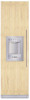
The heightĆadjustable feet at the front and rear can all be adjusted from the front. Front: with openĆended wrench 1/2" (SW13) Rear: with 5/16" (8 mm) hex nut driver via flexible shaft. d CAUTION d Never use a cordless screwdriver! A mark is attached to the appliance base and is used as a standard gage for height adjustment. When adjusting the height, align this mark at a height of 1¼" (32 mm) above the floor. i Note: - Do not twist or jam the appliance inside the cavity! When unscrewing the heightĆadjustable feet, proceed gradually: Always alternate between left and right, left and right, etc.. - The adjustment of the rear feet is facilitated if the appliance is unloaded at the rear. - If using a wooden beam as an alternative antiĆtip device according to point 6 of this installation manual, rotate the appliance all the way towards the wooden beam. 13. Attaching the appliance to the top of the cavity q Unscrew the heightĆadjustable feet until the mark on the base has reached the indicated guide dimension (1¼" / 32 mm). i It is very important to comply with this dimension for the subsequent alignment of the furniture fronts. q Align the furniture fronts with the spirit level. q Screw the attachment plate lugs (top) to the overhead furniture/fixtures. 27
-
 1
1 -
2
-
3
-
4
-
5
-
6
-
7
-
8
-
9
-
10
-
11
-
12
-
13
-
14
-
15
-
16
-
17
-
18
-
19
-
20
-
21
-
 22
22 -
 23
23 -
 24
24 -
 25
25 -
 26
26 -
 27
27 -
 28
28 -
 29
29 -
 30
30 -
 31
31 -
 32
32 -
33
-
34
-
35
-
36
-
37
-
38
-
39
-
40
-
41
-
42
-
43
-
44
-
45
-
46
-
47
-
48
-
49
-
50
-
51
-
52
-
53
-
54
-
55
-
56
-
57
-
58
-
59
-
60
-
61
-
62
-
63
-
64
-
65
-
66
-
67
-
68
-
69
-
70
-
71
-
72
-
73
-
74
-
75
-
76
-
77
-
78
-
79
-
80
-
81
-
82
-
83
-
84
-
85
-
86
-
87
-
88
-
89
-
90
-
91
-
92
-
93
-
94
-
95
-
96
-
97
-
98
-
99
-
100
-
101
-
102
-
103
-
104
-
105
-
106
-
107
-
108
-
109
-
110
-
111
-
112
-
113
-
114
-
115
-
116
-
117
-
118
-
119
-
120
-
121
-
122
-
123
-
124
 |
 |
