Bosch HGS7052UC Installation Instructions - Page 5
Safety & Preparation - dimensions
 |
UPC - 825225843917
View all Bosch HGS7052UC manuals
Add to My Manuals
Save this manual to your list of manuals |
Page 5 highlights
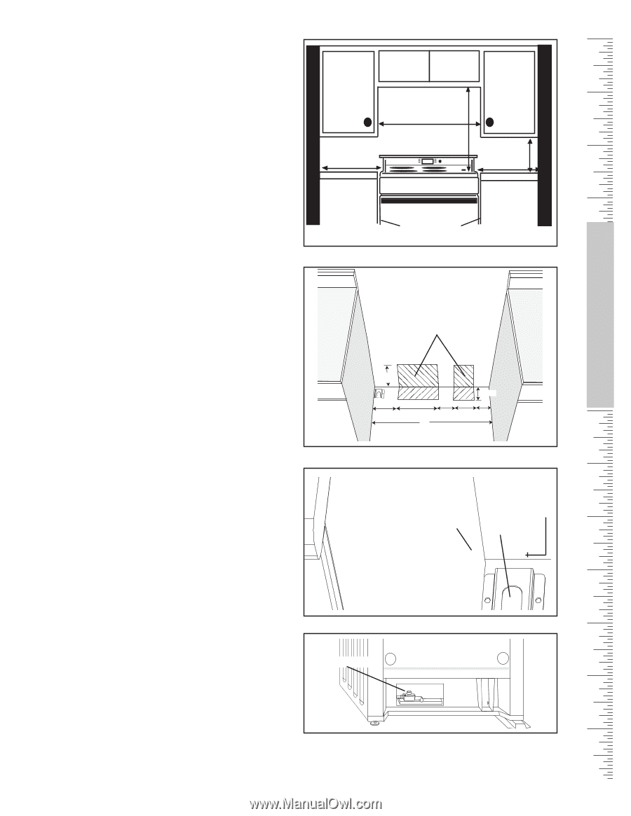
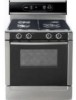
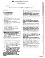
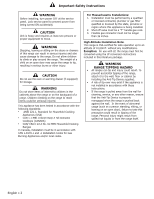
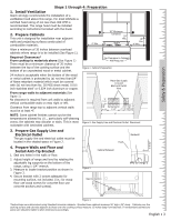
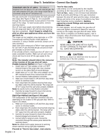
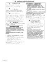
Safety & Preparation Steps 1 through 4: Preparation 1. Install Ventilation Bosch strongly recommends the installation of a ventilation hood above this range. For most kitchens a certified hood rating of not less than 300 CFM is recommended. The range hood must be installed according to instructions furnished with the hood. 2. Prepare Cabinets This unit is designed for installation near adjacent walls and projecting surfaces constructed of combustible materials. 4" Min. 30" Minimum Centered 30" Min. 18" Min. 4" Min. Allow a minimum of 30 inches between overhead cabinets where range is to be installed (See Figure 1). Required Clearances* From cooktop to materials above (See Figure 1) There must be a minimum clearance of 30 inches between the top of the cooking surface and the bottom of an unprotected wood or metal cabinet. No Clearance to Cabinet Wall Required Figure 1: Cabinet Preparation 24 inches is acceptable when the bottom of the wood or metal cabinet is protected by (a) not less than1/4" of flame retardant material which must be covered with (b) not less than No. 28 MSG sheet metal, 0.015 inch stainless steel' or 0.024 inch aluminum or copper. Place Gas Supply Line and Electrical Outlet Here From range walls to adjacent materials (See Figure 1) No clearance is required from unit walls to adjacent vertical combustible walls on rear, right or left. Clearance from range top to adjacent vertical walls must be at least 4". NOTE: Some cabinet finishes cannot survive the temperatures allowed by U.L., particularly self-cleaning ovens; the cabinets may discolor or stain. This is most noticeable with laminated cabinets. 771/12/" 2" 4411//22"" 131311//88"" 3300"" 3311/2/"2" 44"" 33 77//88" " 44 11//22" " Figure 2: Gas Supply Line and Electrical Outlet Placement 3. Prepare Gas Supply Line and Electrical Outlet The gas supply line and electrical outlet must be located in the shaded space in Figure 2. Flush Backwall 4. Prepare Walls and Floor and Install Anti-Tip Bracket 1. Seal any holes in the walls or floor. 2. Adjust height of range and level by rotating the adjustable leg supports on the bottom of the range, using 1-1/4" wrench. 3. Measure to locate bracket position as shown in Figure 3. 4. Secure bracket with 2 screws adequate for mounting surface, not included. (i.e.; for wood floor use wood screws for concrete floor use concrete anchors and screws). Cabinet Sidewall Figure 3 Gas Connection Anti-Tip Device 1 9/16" Figure 4 *Instructions were determined using Standard American cabinets. Standard base cabinets measure 36" high x 24" deep . Cabinets over the cooking surface and cabinets adjacent to those over the cooking surface measure 13 inches deep from backwall. If nonstandard cabinets are used, care should be taken to alter dimensions accordingly. English • 3
-
 1
1 -
 2
2 -
 3
3 -
 4
4 -
 5
5 -
 6
6 -
 7
7 -
 8
8 -
 9
9 -
 10
10 -
 11
11 -
12
-
13
-
14
-
15
-
16
-
17
-
18
-
19
-
20
 |
 |