Bosch HGS7052UC Installation Instructions - Page 6
Step 5, Installation - Connect Gas Supply, Gas Flow to Range, CAUTION - user manual
 |
UPC - 825225843917
View all Bosch HGS7052UC manuals
Add to My Manuals
Save this manual to your list of manuals |
Page 6 highlights
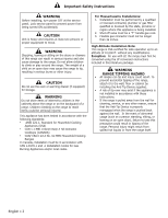
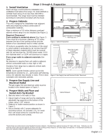
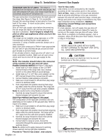
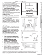
Step 5: Installation - Connect Gas Supply Important note for LP users: The range is shipped from the factory for use with natural gas. For use with propane (LP) gas, your range must first be converted using the LP conversion kit. The gas connection is located below the back panel of the range (See Figure 4, Page 3). It is accessible through the warming drawer access panel or from the back of the range. To reach access panel, remove warming drawer. Shut off main gas supply valve before disconnecting the old range and leave it off until the new hook-up has been completed. Don't forget to relight the pilot on other gas appliances when you turn the gas back on. The range can be installed using rigid pipe or a CSA International-certified flexible metal appliance connector. If using a flexible connector, always use a new connector. Apply pipe joint compound orTeflon* tape appropriate for use with LP gas and Natural gas around all male pipe threads to prevent leaks. If not already present, install gas shut off valve in an easily accessible location. Make sure all users know where and how to shut off the gas supply to the range. Note: The installer should inform the consumer of the location of the gas shut-off valve. Flexible Connector Method (see Figure 5, this page) 1. Install male 1/2" flare adaptor at the 1/2" NPT internal thread of the range inlet. Use a backup wrench on the elbow fitting to avoid damage. 2. Install male 1/2" or 3/4" flare union adapter on the NPT internal thread of the manual shut-off valve. 3. Connect flexible metal appliance connector. 4. Make sure circuit breaker is off and then plug range cord in to electrical outlet. 5. Push range back into position insuring that range leg slides under the anti-tip bracket. The range will sit 3/4" away from the wall when properly installed. Note: Be careful not to crimp flexible connector! 6. Carefully tip range forward to insure that anti-tip bracket engages and prevents tip-over. Rigid Pipe Method (see Figure 6, this page) The configuration of the rigid pipe connection will vary depending on the location of the gas pipe stub. Refer to Figure 6 for details. 1. Make sure circuit breaker is off and then plug range cord in to electrical outlet. 2. Push range back into position insuring that range leg slides under the anti-tip bracket. The range will sit 3/4" away from the wall when properly installed. 3. Carefully tip range forward to insure that anti-tip bracket engages and prevents tip-over. 4. Connect pipe to range at union. Access the connection through the access panel behind the warming drawer. Note: Be careful not to apply pressure to warming drawer element during rigid pipe installation. Proceed to "Test for Gas Leaks", next column. English • 4 Test for Gas Leaks Leak testing is to be conducted by the installer according to the instructions given in this section. Turn on Gas. Apply a non-corrosive leak detection fluid to all joints and fittings in the gas connection between the shut-off valve and the range. Include gas fittings and joints in the range if connections may have been disturbed during installation. Bubbles appearing around fittings and connections indicate a leak. If a leak appears, turn off supply line gas shut-off valve and tighten connections. Retest for leaks by turning on the supply line gas shut-off valve. When leak check is complete (no bubbles appear), test is complete. Wipe off all detection fluid residue. Proceed to Step 6: Final Steps. CAUTION NEVER CHECK FOR LEAKS WITH A FLAME. DO NOT CONTINUE TO THE NEXT STEP UNTIL ALL LEAKS ARE ELIMINATED. CAUTION Before you plug in an electrical cord, be sure all controls are in the OFF position. Gas ShutOff Valve Regulator Flexible Connector Figure 5: Flexible Connector Method elbow gas shut off valve elbow nipple union nipple elbow: connect to regulator here nipple 1/2" to 3/4" gas pipe Gas Flow to Range Figure 6: Rigid Pipe Method
-
 1
1 -
 2
2 -
 3
3 -
 4
4 -
 5
5 -
 6
6 -
 7
7 -
 8
8 -
 9
9 -
 10
10 -
 11
11 -
 12
12 -
13
-
14
-
15
-
16
-
17
-
18
-
19
-
20
 |
 |