Bosch VDC-455V04-20S Installation Instructions - Page 13
Connection and set-up
 |
View all Bosch VDC-455V04-20S manuals
Add to My Manuals
Save this manual to your list of manuals |
Page 13 highlights
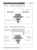
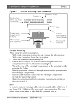
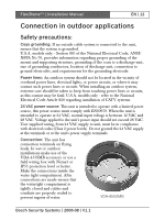
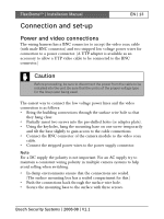
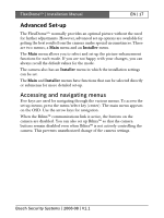
FlexiDomeXT+ | Installation Manual Connection and set-up EN | 13 Power and video connections The wiring harness has a BNC connector to accept the video coax cable (with male BNC connector) and two stripped low voltage power wires for connection to a power connector. (A UTP adapter is available as an accessory to allow a UTP video cable to be connected to the BNC connector.) Caution Before proceeding, be sure to disconnect the power from the cable to be installed into the unit. Be sure that the unit is of the proper voltage type for the line power being used. The easiest way to connect the low voltage power lines and the video connection is as follows: • Bring the building connections through the surface wire hole so that they hang clear. • Partially insert two screws into the pre-drilled holes (or adapter plate). • Using the keyholes, hang the mounting base on one screw temporarily and tilt the base slightly to gain access to the cable connections. • Connect the BNC connector of the camera module to the video coax cable. • Connect the stripped power wires to the power supply connector. Note For a DC supply the polarity is not important. For an AC supply try to maintain a consistent wiring polarity in multiple camera systems to help avoid rolling when switching. • In damp environments ensure that the connections are sealed. (The surface mounting box has a sealed compartment for this.) • Push the connections back through the surface wire hole. • Secure the mounting base to the surface with three screws. Bosch Security Systems | 2008-08 | V1.1
-
 1
1 -
2
-
3
-
4
-
5
-
6
-
7
-
 8
8 -
 9
9 -
 10
10 -
 11
11 -
 12
12 -
 13
13 -
 14
14 -
 15
15 -
 16
16 -
 17
17 -
 18
18 -
19
-
20
-
21
-
22
-
23
-
24
-
25
-
26
-
27
-
28
-
29
-
30
-
31
-
32
-
33
-
34
-
35
-
36
-
37
-
38
-
39
-
40
-
41
-
42
-
43
-
44
-
45
-
46
-
47
-
48
-
49
-
50
-
51
-
52
-
53
-
54
-
55
-
56
-
57
-
58
-
59
-
60
-
61
-
62
-
63
-
64
-
65
-
66
-
67
-
68
-
69
-
70
-
71
-
72
-
73
-
74
-
75
-
76
-
77
-
78
-
79
-
80
-
81
-
82
-
83
-
84
-
85
-
86
-
87
-
88
-
89
-
90
-
91
-
92
-
93
-
94
-
95
-
96
-
97
-
98
-
99
-
100
-
101
-
102
-
103
-
104
-
105
-
106
-
107
-
108
-
109
-
110
-
111
-
112
-
113
-
114
-
115
-
116
-
117
-
118
-
119
-
120
-
121
-
122
-
123
-
124
-
125
-
126
-
127
-
128
-
129
-
130
-
131
-
132
-
133
-
134
-
135
-
136
-
137
-
138
-
139
-
140
-
141
-
142
-
143
-
144
-
145
-
146
-
147
-
148
-
149
-
150
-
151
-
152
-
153
-
154
-
155
-
156
-
157
-
158
-
159
-
160
-
161
-
162
-
163
-
164
-
165
-
166
-
167
-
168
-
169
-
170
-
171
-
172
-
173
-
174
-
175
-
176
-
177
-
178
-
179
-
180
-
181
-
182
-
183
-
184
-
185
-
186
-
187
-
188
-
189
-
190
-
191
-
192
-
193
-
194
-
195
-
196
-
197
-
198
-
199
-
200
-
201
-
202
-
203
-
204
-
205
-
206
-
207
-
208
-
209
-
210
 |
 |