Bosch VDC-455V04-20S Installation Instructions - Page 15
Camera positioning, Focal length and focus
 |
View all Bosch VDC-455V04-20S manuals
Add to My Manuals
Save this manual to your list of manuals |
Page 15 highlights
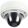
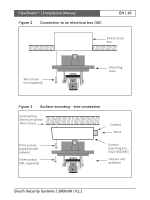
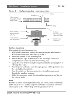
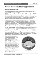
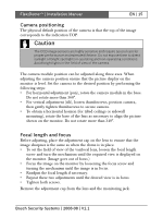
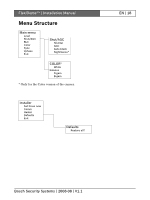
FlexiDomeXT+ | Installation Manual EN | 15 Camera positioning The physical default position of the camera is that the top of the image corresponds to the indication TOP. Caution The CCD image sensors are highly sensitive and require special care for proper performance and extended lifetime. Do not expose them to direct sunlight or bright spotlights in operating and non-operating conditions. Avoid bright lights in the field of view of the camera. The camera module position can be adjusted along three axes. When adjusting the camera position ensure that the picture display on the monitor is level. Set the camera to the desired position by performing the following steps: • For horizontal adjustment (pan), rotate the camera module in the base. Do not rotate more than 360°. • For vertical adjustment (tilt), loosen thumbscrews, position camera, then gently tighten thumbscrews to secure camera. • To obtain a horizontal horizon (for tilted ceilings or sidewall mounting), rotate the base of the lens as necessary to align the picture shown on the monitor. Do not rotate more than 340°. Focal length and focus Before adjusting, place the adjustment cap on the lens to ensure that the image sharpnes is the same as when the dome is in place. • To set the field of view of the varifocal lens, loosen the focal length screw and turn the mechanism until the required view is displayed on the monitor. (Image goes out of focus.) • Focus the image on the monitor by loosening the focus screw and turning the mechanism until the image is in focus. • Readjust the focal length if necessary. • Repeat these two adjustments until the desired view is in focus. • Tighten both screws. Remove the adjustment cap from the lens and the monitoring jack. Bosch Security Systems | 2008-08 | V1.1
-
 1
1 -
2
-
3
-
4
-
5
-
6
-
7
-
8
-
9
-
 10
10 -
 11
11 -
 12
12 -
 13
13 -
 14
14 -
 15
15 -
 16
16 -
 17
17 -
 18
18 -
 19
19 -
 20
20 -
21
-
22
-
23
-
24
-
25
-
26
-
27
-
28
-
29
-
30
-
31
-
32
-
33
-
34
-
35
-
36
-
37
-
38
-
39
-
40
-
41
-
42
-
43
-
44
-
45
-
46
-
47
-
48
-
49
-
50
-
51
-
52
-
53
-
54
-
55
-
56
-
57
-
58
-
59
-
60
-
61
-
62
-
63
-
64
-
65
-
66
-
67
-
68
-
69
-
70
-
71
-
72
-
73
-
74
-
75
-
76
-
77
-
78
-
79
-
80
-
81
-
82
-
83
-
84
-
85
-
86
-
87
-
88
-
89
-
90
-
91
-
92
-
93
-
94
-
95
-
96
-
97
-
98
-
99
-
100
-
101
-
102
-
103
-
104
-
105
-
106
-
107
-
108
-
109
-
110
-
111
-
112
-
113
-
114
-
115
-
116
-
117
-
118
-
119
-
120
-
121
-
122
-
123
-
124
-
125
-
126
-
127
-
128
-
129
-
130
-
131
-
132
-
133
-
134
-
135
-
136
-
137
-
138
-
139
-
140
-
141
-
142
-
143
-
144
-
145
-
146
-
147
-
148
-
149
-
150
-
151
-
152
-
153
-
154
-
155
-
156
-
157
-
158
-
159
-
160
-
161
-
162
-
163
-
164
-
165
-
166
-
167
-
168
-
169
-
170
-
171
-
172
-
173
-
174
-
175
-
176
-
177
-
178
-
179
-
180
-
181
-
182
-
183
-
184
-
185
-
186
-
187
-
188
-
189
-
190
-
191
-
192
-
193
-
194
-
195
-
196
-
197
-
198
-
199
-
200
-
201
-
202
-
203
-
204
-
205
-
206
-
207
-
208
-
209
-
210
 |
 |