Bosch VDC-455V04-20S Installation Instructions - Page 9
Mounting the unit
 |
View all Bosch VDC-455V04-20S manuals
Add to My Manuals
Save this manual to your list of manuals |
Page 9 highlights
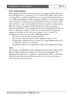
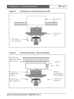
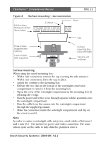
FlexiDomeXT+ | Installation Manual EN | 9 Mounting the unit The unit may be mounted in several different ways depending on the type of surface, whether an electrical box is used and whether the connection is via the rear or the side (surface mounted). Caution Installation should only be performed by qualified service personnel in accordance with the National Electrical Code or applicable local codes. If the unit is surface mounted, use the separately available raised mounting base (VDA-455SMB) and mount the unit onto this base. Tips • Refer to the dimensions drawing to find the exact position of the screw holes and the entry hole for the wires. • Partially screw in two screws for the keyholes and use them to temporarily hang the camera while the connections are made. The following figures show the different ways of mounting the unit. Figure 1 Rear connection - hollow surface Strong surface (four pre-drilled 8mm holes) Wires Three screws (supplied) Mounting base Bosch Security Systems | 2008-08 | V1.1
-
 1
1 -
2
-
3
-
 4
4 -
 5
5 -
 6
6 -
 7
7 -
 8
8 -
 9
9 -
 10
10 -
 11
11 -
 12
12 -
 13
13 -
 14
14 -
15
-
16
-
17
-
18
-
19
-
20
-
21
-
22
-
23
-
24
-
25
-
26
-
27
-
28
-
29
-
30
-
31
-
32
-
33
-
34
-
35
-
36
-
37
-
38
-
39
-
40
-
41
-
42
-
43
-
44
-
45
-
46
-
47
-
48
-
49
-
50
-
51
-
52
-
53
-
54
-
55
-
56
-
57
-
58
-
59
-
60
-
61
-
62
-
63
-
64
-
65
-
66
-
67
-
68
-
69
-
70
-
71
-
72
-
73
-
74
-
75
-
76
-
77
-
78
-
79
-
80
-
81
-
82
-
83
-
84
-
85
-
86
-
87
-
88
-
89
-
90
-
91
-
92
-
93
-
94
-
95
-
96
-
97
-
98
-
99
-
100
-
101
-
102
-
103
-
104
-
105
-
106
-
107
-
108
-
109
-
110
-
111
-
112
-
113
-
114
-
115
-
116
-
117
-
118
-
119
-
120
-
121
-
122
-
123
-
124
-
125
-
126
-
127
-
128
-
129
-
130
-
131
-
132
-
133
-
134
-
135
-
136
-
137
-
138
-
139
-
140
-
141
-
142
-
143
-
144
-
145
-
146
-
147
-
148
-
149
-
150
-
151
-
152
-
153
-
154
-
155
-
156
-
157
-
158
-
159
-
160
-
161
-
162
-
163
-
164
-
165
-
166
-
167
-
168
-
169
-
170
-
171
-
172
-
173
-
174
-
175
-
176
-
177
-
178
-
179
-
180
-
181
-
182
-
183
-
184
-
185
-
186
-
187
-
188
-
189
-
190
-
191
-
192
-
193
-
194
-
195
-
196
-
197
-
198
-
199
-
200
-
201
-
202
-
203
-
204
-
205
-
206
-
207
-
208
-
209
-
210
 |
 |