Bosch VDN-498V03-21 User Manual
Bosch VDN-498V03-21 Manual
 |
View all Bosch VDN-498V03-21 manuals
Add to My Manuals
Save this manual to your list of manuals |
Bosch VDN-498V03-21 manual content summary:
- Bosch VDN-498V03-21 | User Manual - Page 1
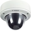
FlexiDome2X VDN-0498 en Installation Manual - Bosch VDN-498V03-21 | User Manual - Page 2
- Bosch VDN-498V03-21 | User Manual - Page 3
instructions Connection in outdoor applications Safety precautions FCC information UL certification Bosch notice 2 Introduction 2.1 Features 3 3.1 3.2 3.3 3.3.1 3.3.2 3.3.3 Installation Install menu Bosch Security Systems Installation Manual 5 5 6 7 7 9 11 11 13 13 15 15 16 17 17 18 19 21 21 - Bosch VDN-498V03-21 | User Manual - Page 4
Install menu structure Language submenu Connections submenu Test signal submenu Camera ID submenu Privacy masking submenu Defaults submenu 6 Troubleshooting 6.1 Resolving problems 6.2 Customer service 49 51 51 53 55 57 AR18-08-B010 | v1.0 | 2009.03 Installation Manual Bosch Security Systems - Bosch VDN-498V03-21 | User Manual - Page 5
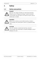
bodily injury. CAUTION! ! Low risk: Indicates a potentially hazardous situation. If not avoided, this could result in property damage or risk of damage to the unit. Bosch Security Systems Installation Manual AR18-08-B010 | v1.0 | 2009.03 - Bosch VDN-498V03-21 | User Manual - Page 6
unit yourself. Refer all servicing to qualified service personnel. 8. Replacement parts - Use only replacement parts specified by the manufacturer. 9. Installation - Install in accordance with the manufacturer's instructions and in accordance with applicable local codes. 10. Attachments, changes or - Bosch VDN-498V03-21 | User Manual - Page 7
, ANSI/NFPA No.70, provides information regarding proper grounding of the mount and supporting structure, grounding of the coax to a discharge unit, size of grounding conductors, properly sealed to prevent ingress of water. Bosch Security Systems Installation Manual AR18-08-B010 | v1.0 | 2009.03 - Bosch VDN-498V03-21 | User Manual - Page 8
a SELV - Class 2 unit (Safety Extra Low Voltage - Limited Power Source). Disposal - Your Bosch product was developed and manufactured with high-quality material and components that can be recycled and reused. 2002/96/EC AR18-08-B010 | v1.0 | 2009.03 Installation Manual Bosch Security Systems - Bosch VDN-498V03-21 | User Manual - Page 9
the Federal Communications Commission, helpful: How to Identify and Resolve Radio-TV Interference Problems. This booklet is available from the U.S. Government Printing Office, Washington, DC 20402, Stock No. 004-000-00345-4. Bosch Security Systems Installation Manual AR18-08-B010 | v1.0 | 2009.03 - Bosch VDN-498V03-21 | User Manual - Page 10
10 en cas d'installation ou d'utilisation non conforme aux instructions, engendrer des Problems (Comment identifier et résoudre les problèmes d'interférences de radio et de télévision). Cette brochure est disponible auprès du U.S. Government AR18-08-B010 | v1.0 | 2009.03 Installation Manual Bosch - Bosch VDN-498V03-21 | User Manual - Page 11
FlexiDome2X Safety | en 11 Printing Office, Washington, DC 20402, États-Unis, sous la référence n° 1.6 Bosch notice More information For more information please contact the nearest Bosch Security Systems location or visit www.boschsecurity.com Bosch Security Systems Installation Manual AR18- - Bosch VDN-498V03-21 | User Manual - Page 12
(20-bit) digital signal processing and a wide dynamic range CCD sensor for outstanding picture performance. The FlexiDome2X camera is easy to install and Multiple language on-screen display - Built-in test pattern generator Bosch Security Systems Installation Manual AR18-08-B010 | v1.0 | 2009.03 - Bosch VDN-498V03-21 | User Manual - Page 13
instructions - Quick install instructions - CD ROM - Installation Instructions service personnel in accordance with the National Electrical Code or applicable local codes. CAUTION! ! The camera module is a sensitive device and must be handled carefully. Bosch Security Systems Installation Manual - Bosch VDN-498V03-21 | User Manual - Page 14
16 en | Installation FlexiDome2X 3.2 Disassembly The flush-mount version consists of the following parts: Camera module and mounting base Inner liner liner (with sealing ring) Trim ring Dome Figure 3.2 Surface-mount AR18-08-B010 | v1.0 | 2009.03 Installation Manual Bosch Security Systems - Bosch VDN-498V03-21 | User Manual - Page 15
FlexiDome2X Installation | en 17 To disassemble the unit proceed as follows: 1. Use the special screwdriver bit to loosen screws for the keyholes and use them to temporarily hang the camera while the connections are made. Bosch Security Systems Installation Manual AR18-08-B010 | v1.0 | 2009.03 - Bosch VDN-498V03-21 | User Manual - Page 16
18 en | Installation 3.3.2 Flush mounting FlexiDome2X Figure 3.3 Flush mounting - hollow surface 1. Solid surface (pre-drill three 8mm holes and screws (not supplied) 2. Integrated camera unit and base 3. 4S electrical box AR18-08-B010 | v1.0 | 2009.03 Installation Manual Bosch Security Systems - Bosch VDN-498V03-21 | User Manual - Page 17
FlexiDome2X Installation | en 19 3.3.3 Surface mounting When using the surface mounting box: - With a side connection, remove video connection. Note: Use some silicon spray on the cable to help slide the grommets onto it. Bosch Security Systems Installation Manual AR18-08-B010 | v1.0 | 2009.03 - Bosch VDN-498V03-21 | User Manual - Page 18
20 en | Installation FlexiDome2X Figure 3.6 Surface mounting - side connection 1. Solid surface (pre-drill three 8mm holes and fit supplied plugs) box (VDA-455SMB) 6. Cap (remove for side-entry cables) 7. Conduit 8. Cables AR18-08-B010 | v1.0 | 2009.03 Installation Manual Bosch Security Systems - Bosch VDN-498V03-21 | User Manual - Page 19
FlexiDome2X Connection and set-up | en 21 4 Connection and set-up 4.1 ! Power and video connections The wiring harness has a BNC wiring polarity in multiple camera systems to help avoid potential camera video rolling. Bosch Security Systems Installation Manual AR18-08-B010 | v1.0 | 2009.03 - Bosch VDN-498V03-21 | User Manual - Page 20
through the surface cable hole. 8. Secure the mounting base of the camera module to the surface with three screws. AR18-08-B010 | v1.0 | 2009.03 Installation Manual Bosch Security Systems - Bosch VDN-498V03-21 | User Manual - Page 21
the S1460 cable is attached, there is no video available on the BNC connector to avoid interference. A C Figure 4.1 Camera parts 1. Heater 2. Monitor jack socket 3. Thumbwheels Bosch Security Systems Installation Manual B AR18-08-B010 | v1.0 | 2009.03 - Bosch VDN-498V03-21 | User Manual - Page 22
tilt axis (B), loosen thumbwheels, position camera, then gently tighten thumbwheels to secure camera. Do not rotate more than 90°. AR18-08-B010 | v1.0 | 2009.03 Installation Manual Bosch Security Systems - Bosch VDN-498V03-21 | User Manual - Page 23
the next or previous menu. - Press the menu/select key for approximately 2 seconds to open the Install menu. - Use the up or down keys to scroll through a menu. - Use the left key until the menu display disappears. Bosch Security Systems Installation Manual AR18-08-B010 | v1.0 | 2009.03 - Bosch VDN-498V03-21 | User Manual - Page 24
cap from the lens and disconnect the monitor. 4.2.4 Heater When using the camera at low temperatures, set the heater setting to Auto in the Install menu. The heater turns on at ambient temperatures below 0°C (+32°F). AR18-08-B010 | v1.0 | 2009.03 Installation Manual Bosch Security Systems - Bosch VDN-498V03-21 | User Manual - Page 25
in the trim ring with the threaded ends in the mounting base. 5. Use the special screwdriver bit supplied to tighten the three tamper-resistant screws. Bosch Security Systems Installation Manual AR18-08-B010 | v1.0 | 2009.03 - Bosch VDN-498V03-21 | User Manual - Page 26
the default values for the mode. Install menu The camera also has an Install menu in which the installation settings can be set. To access the Install menu, press the menu/select button (center) for longer than 1 second. Bosch Security Systems Installation Manual AR18-08-B010 | v1.0 | 2009.03 - Bosch VDN-498V03-21 | User Manual - Page 27
can select one of the six pre-defined modes in the Install/Mode submenu. The modes are defined as follows: 1. 24-hour Default installation mode to provide stable pictures over a 24-hour period. connected to a CRT monitor. AR18-08-B010 | v1.0 | 2009.03 Installation Manual Bosch Security Systems - Bosch VDN-498V03-21 | User Manual - Page 28
to disable the local keys on the camera. To avoid loss of communication on an installed camera, the Communication On/Off selection is not available while using remote control. This the buttons on the camera are disabled. Bosch Security Systems Installation Manual AR18-08-B010 | v1.0 | 2009.03 - Bosch VDN-498V03-21 | User Manual - Page 29
name (11 characters maximum) Copy active mode Available mode numbers Copies current mode settings to the mode number selected. Default mode Submenu Restores camera to the factory default settings. EXIT Returns to main menu. AR18-08-B010 | v1.0 | 2009.03 Installation Manual Bosch Security - Bosch VDN-498V03-21 | User Manual - Page 30
compensate for compression methods. Off - The camera output is optimized for connection to an analog system (matrix switcher or monitor. EXIT Returns to main menu. Bosch Security Systems Installation Manual AR18-08-B010 | v1.0 | 2009.03 - Bosch VDN-498V03-21 | User Manual - Page 31
Displays the actual AGC value from the camera to help compare gain level with lighting levels and picture performance. AR18-08-B010 | v1.0 | 2009.03 Installation Manual Bosch Security Systems - Bosch VDN-498V03-21 | User Manual - Page 32
means that the camera switches to monochrome at a lower light level. A high (positive) value means that the camera switches to monochrome at a higher light level. Bosch Security Systems Installation Manual AR18-08-B010 | v1.0 | 2009.03 - Bosch VDN-498V03-21 | User Manual - Page 33
color burst remains active even in monochrome mode (required by some DVRs and IP encoders). Returns to main menu. AR18-08-B010 | v1.0 | 2009.03 Installation Manual Bosch Security Systems - Bosch VDN-498V03-21 | User Manual - Page 34
less sharp. Increasing sharpness brings out more detail. Extra sharpness can enhance the details of license plates, facial features and the edges of certain surfaces. Bosch Security Systems Installation Manual AR18-08-B010 | v1.0 | 2009.03 - Bosch VDN-498V03-21 | User Manual - Page 35
speed of the white balance control loop. Red gain -5 to +5 -50 to +50 ATW and AWBhold - adjusts the Red gain to optimize the white point. Manual - adjusts the Red gain. AR18-08-B010 | v1.0 | 2009.03 Installation Manual Bosch Security Systems - Bosch VDN-498V03-21 | User Manual - Page 36
Description ATW and AWBhold - adjusts the B gain to optimize the white point. Manual - adjusts the Blue gain. Manual - adjusts the Green gain. Adjusts the color saturation. -15 gives a monochrome ). Returns to main menu. Bosch Security Systems Installation Manual AR18-08-B010 | v1.0 | 2009.03 - Bosch VDN-498V03-21 | User Manual - Page 37
-triggered alarm output of the camera to a monitored alarm system as the false-positive alarms may be considered a nuisance. AR18-08-B010 | v1.0 | 2009.03 Installation Manual Bosch Security Systems - Bosch VDN-498V03-21 | User Manual - Page 38
masking area Returns all settings for all modes to factory defaults Select to close the Install menu and open the lens wizard. Adjust the focus as described in Section 4.2.3 Focal lens wizard and open the Install menu again. Bosch Security Systems Installation Manual AR18-08-B010 | v1.0 | 2009.03 - Bosch VDN-498V03-21 | User Manual - Page 39
menus on the OSD in the choosen language. EXIT Returns to Install menu. 5.6.2 Item Connections submenu Selection Description Notch filter On, Off Off, Bilinx communications is disabled. EXIT Returns to Install menu. AR18-08-B010 | v1.0 | 2009.03 Installation Manual Bosch Security Systems - Bosch VDN-498V03-21 | User Manual - Page 40
video test signal. Test pattern Color bars 100%, Grayscale 11step, Sawtooth 2H, Checker board, Cross hatch, UV plane Select the desired test pattern to help installation and fault-finding. EXIT Returns to Install menu. Bosch Security Systems Installation Manual AR18-08-B010 | v1.0 | 2009.03 - Bosch VDN-498V03-21 | User Manual - Page 41
mode ID Off, Top left, Top right, Bottom left, Bottom right Camera mode is displayed on the screen in the selected position. EXIT Returns to Install menu. AR18-08-B010 | v1.0 | 2009.03 Installation Manual Bosch Security Systems - Bosch VDN-498V03-21 | User Manual - Page 42
modes to their default (factory) values. Select YES then press the Menu/Select button to restore all values. When completed the message RESTORED! is shown. Bosch Security Systems Installation Manual AR18-08-B010 | v1.0 | 2009.03 - Bosch VDN-498V03-21 | User Manual - Page 43
FlexiDome2X 6 Troubleshooting Troubleshooting | en 47 6.1 Resolving problems The following table is opening the Install menu. Note down this information and the information found on the camera label before contacting customer service. Bosch Security Systems Installation Manual AR18-08-B010 - Bosch VDN-498V03-21 | User Manual - Page 44
guide. The unit contains environmentally hazardous materials that must be disposed of according to law. Defective or superfluous devices and parts should be disposed of professionally or taken to your local collection point for hazardous materials. Bosch Security Systems Installation Manual - Bosch VDN-498V03-21 | User Manual - Page 45
Active pixels Rated supply voltage VDN-498V03 2.8 to 10 mm VDN-498V09 9 to 22 mm F1.2 F1.4 0.28 (0.027) lx (fc) 30IRE 0.32 (0.03) lx (fc) 30IRE 0.099 (0.0092) mono 0.11 (0.01) mono 752 x 582 (PAL - 11), 768 x 494 (NTSC - 21) 24 VAC (±10%) or +12 VDC (±10%) All versions Imager 1/3-inch - Bosch VDN-498V03-21 | User Manual - Page 46
Color bars 100%, Greyscale 11-step, Sawtooth 2H, Checker board, Cross hatch, UV plane Video 21 lb) Operating temperature -30 °C to +55 °C (-22 °F to +131 °F) (-50 °C [-58 °F] with heater enabled) Controls OSD with softkey operation AR18-08-B010 | v1.0 | 2009.03 Installation Manual Bosch - Bosch VDN-498V03-21 | User Manual - Page 47
FlexiDome2X 8.1.1 Dimensions 57.6 (2.27) Technical Data | en 53 57.6 (2.27) 33.3 (1.31) 66.5 (2.62) 121 (4.77) 85 (3.35) 39.5 (1.56) 95 (3.7) 158 (6.22) Figure 8.1 Dimensions - Flush-mount mm (in) Bosch Security Systems Installation Manual AR18-08-B010 | v1.0 | 2009.03 - Bosch VDN-498V03-21 | User Manual - Page 48
54 en | Technical Data 53.3 (2.1) 53.3 (2.1) FlexiDome2X 30.8 (1.21) 35 (1.38) 121 (4.77) 130.5 (5.14) 158 (6.22) Figure 8.2 Dimensions - Surface-mount mm (in) AR18-08-B010 | v1.0 | 2009.03 Installation Manual Bosch Security Systems - Bosch VDN-498V03-21 | User Manual - Page 49
mount - Pendant ceiling mount - Corner mount - Bilinx communication interface box and software Contact a Bosch representative in your area for the latest available accessories or visit our website at www.boschsecurity.com Bosch Security Systems Installation Manual AR18-08-B010 | v1.0 | 2009.03 - Bosch VDN-498V03-21 | User Manual - Page 50
. This can be done electronically or by means of an iris control. Auto White Balance (AWB) A feature that allows a color camera to automatically adjust its Bosch Security Systems Installation Manual AR18-08-B010 | v1.0 | 2009.03 - Bosch VDN-498V03-21 | User Manual - Page 51
is quoted in inches, for example 1/3 or 1/2 inch. Color Temperature A measure of the relative color of illumination. Generally used AR18-08-B010 | v1.0 | 2009.03 Installation Manual Bosch Security Systems - Bosch VDN-498V03-21 | User Manual - Page 52
- Automatic Electronic Shutter) adjusts the camera shutter speed to compensate for lighting changes. In some cases this can eliminate the need for an autoiris lens. Bosch Security Systems Installation Manual AR18-08-B010 | v1.0 | 2009.03 - Bosch VDN-498V03-21 | User Manual - Page 53
into 140 equal units 140 IRE equals 1V peak-to-peak. The range of active video is 100 IRE. AR18-08-B010 | v1.0 | 2009.03 Installation Manual Bosch Security Systems - Bosch VDN-498V03-21 | User Manual - Page 54
in an image. For analog systems this is typically measured in horizontal Television Lines or TVL. The higher the TVL rating, the higher the resolution. Bosch Security Systems Installation Manual AR18-08-B010 | v1.0 | 2009.03 - Bosch VDN-498V03-21 | User Manual - Page 55
cable. UTP is the primary wire type for telephone usage and the most commonly used type of networking cable. AR18-08-B010 | v1.0 | 2009.03 Installation Manual Bosch Security Systems - Bosch VDN-498V03-21 | User Manual - Page 56
levels. A scene with both very low and very high illumination levels requires a camera with a wide dynamic range to handle it correctly and produce a useful image. Bosch Security Systems Installation Manual AR18-08-B010 | v1.0 | 2009.03 - Bosch VDN-498V03-21 | User Manual - Page 57
- Bosch VDN-498V03-21 | User Manual - Page 58
Bosch Security Systems www.boschsecurity.com © Bosch Security Systems, 2009
-
 1
1 -
 2
2 -
 3
3 -
 4
4 -
 5
5 -
 6
6 -
 7
7 -
8
-
9
-
10
-
11
-
12
-
13
-
14
-
15
-
16
-
17
-
18
-
19
-
20
-
21
-
22
-
23
-
24
-
25
-
26
-
27
-
28
-
29
-
30
-
31
-
32
-
33
-
34
-
35
-
36
-
37
-
38
-
39
-
40
-
41
-
42
-
43
-
44
-
45
-
46
-
47
-
48
-
49
-
50
-
51
-
52
-
53
-
54
-
55
-
56
-
57
-
58
 |
 |
FlexiDome2X
VDN-0498
en
Installation Manual