Bosch WTMC3521UC Operating, Care, Installation (all languages) - Page 7
Warning, Caution, Warning - not drying
 |
View all Bosch WTMC3521UC manuals
Add to My Manuals
Save this manual to your list of manuals |
Page 7 highlights
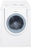
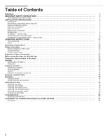
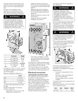
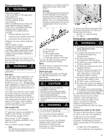
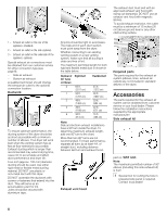
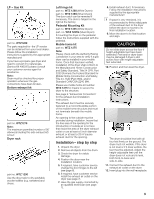
Gas connection d WARNING d Explosion hazard! Use a new AGA or CSA approved gas supply line. Install a shutĆoff valve. Securely tighten all gas connections. Have a qualified person make sure gas pressure does not exceed 14 in. W.C./ 3.49 kPa/ 0.506 psig. (Natural and Propane Gas). Example of a qualified person include: - licensed heating personnel, - authorized gas supplier personnel, - authorized service personnel. Failure to do can result in explosion or fire. Risk of death or injury! All gas line connections must be teĆ sted for leaks prior to appliance operation. Apply soapy water to gas line connections and check for forĆ mation of new bubbles. Bubbles inĆ dicate leak! When installing the gas supply to the gas dryer inlet pipe, do not exceed 310 lbf in (35 Nm). d WARNING d Never use an open flame to test for gas leaks. Gas type This gas dryer when equipped for use with NATURAL GAS, will employ an orifice size 46 and have a gas outlet pressure of 3.5 in. W.C. This gas dryer when equipped for use with PROPANE GAS, will employ an orifice size of 1.21 mm, and have a gas outlet pressure of 11 in. W.C. Your dryer must have the correct valve for the type of gas in your home. Valve information is located on the rating plate behind the door below the drum. If the ratingĆplate information does not agree with the type of gas available, contact your dealer or our customer service team (see page 21). Gas supply line 1/2" I.D. pipe is recommended. 3/8" approved tubing is acceptable for lengths under 20 ft (6.1 m) if local codes and gas supplier permit. Must include 1/8" NPT plugged tapping, immediately upstream of the gas connection. A shut off valve must be included: - USA: An individual manual shutĆoff valve must be installed within 6 ft (1.8 m) of the dryer in accordance with the National Fuel Gas Code, ANSI Z223.1. - Canada: An individual manual shutĆoff valve must be installed in accordance with the B149, Installation Codes, CAN/CSA B149.1 and CAN/CSA B149.2. It is recommended that an individual manual shutĆoff valve be installed within 6 ft (1.8 m) of the dryer. 5 43 2 1 1 1 ć 1/2" NPT gas supply line 2 ć Gas shutĆoff valve 3 ć 1/8" NPT plugged tapping 4 ć 3/8" pipe to flare adapter fitting 5 ć 3/8" flexible gas connector (to the dryer) The shutĆoff valve should be easy to reach for opening and closing. Note: The dryer must be checked for proper operation whenever the gas connections have been broken. Dryer gas pipe The gas pipe that comes out through the rear of the dryer has a 3/8" male pipe thread. Connection of the dryer d CAUTION d Connection must be made by a qualified technician. The dryer must be disconnected from the gas supply piping system during testing pressure. When using for the first time make sure that there is no air in the piping system. d WARNING d Do not use copper pipes and tubing if connected to natural gas. The connection may be different, according to the supply line type, size and location. If local codes permit, use a flexible stainless steel connector (Design certified by the America Gas Association or CSA International) to connect the dryer. 1 2 To reduce the distance between body sheet and wall install a 3/8" elbow on the gas pipe of the dryer. 1 ć gas pipe (3/8" male pipe thread) 2 ć 3/8" elbow Exhaust air connection d WARNING! d 1. To reduce the risk of fire, this dryer MUST BE EXHAUSTED OUTDOORS. 2. To reduce the risk of fire, do not use ductwork longer than recommended. 3. DO NOT use a plastic or nonĆmetal duct with this dryer. 4. DO NOT use a duct smaller than 4 inches in diameter. 5. DO NOT use exhaust hoods with magnetic latches. 6. DO NOT exhaust the dryer into a chimney, furnace cold air duct, attic, crawl space, or any other ductwork used for venting. 7. DO NOT install a flexible duct in an enclosed wall, ceiling or floor. 8. DO NOT crush or kink the duct. 9. Do clean and inspect the exhaust system on a regular basis; at least once a year. 10. The exhaust duct must terminate in a manner to prevent back drafts or entry of birds or other wildlife. The Bosch dryer must be vented outdoors. To prevent buildĆup of moisture and accumulation of lint indoors, as well as to maintain maximum drying efficiency, it is recommended that the dryer is vented outdoors. Exhaust air outlet on the dryer The dryer is delivered with an exhaust air outlet on the rear of the appliance. To take account of the spatial requirements and an existing exhaust air system, the following connection options are possible for the exhaust air outlet: - on right side of the appliance, - on the underside of the appliance. 7
-
 1
1 -
 2
2 -
 3
3 -
 4
4 -
 5
5 -
 6
6 -
 7
7 -
 8
8 -
 9
9 -
 10
10 -
 11
11 -
 12
12 -
13
-
14
-
15
-
16
-
17
-
18
-
19
-
20
-
21
-
22
-
23
-
24
-
25
-
26
-
27
-
28
-
29
-
30
-
31
-
32
-
33
-
34
-
35
-
36
-
37
-
38
-
39
-
40
-
41
-
42
-
43
-
44
-
45
-
46
-
47
-
48
-
49
-
50
-
51
-
52
-
53
-
54
-
55
-
56
-
57
-
58
-
59
-
60
-
61
-
62
-
63
-
64
-
65
-
66
-
67
-
68
 |
 |