Bosch WTMC3521UC Operating, Care, Installation (all languages) - Page 8
Accessories - parts
 |
View all Bosch WTMC3521UC manuals
Add to My Manuals
Save this manual to your list of manuals |
Page 8 highlights
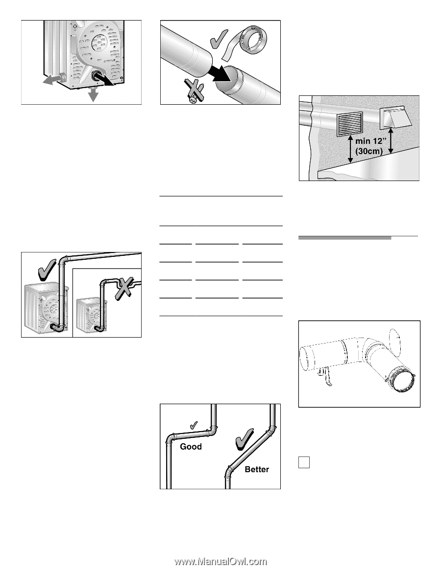
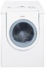
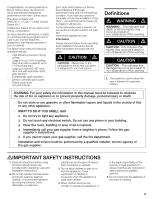
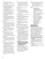
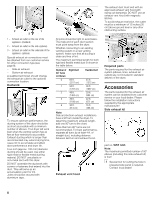
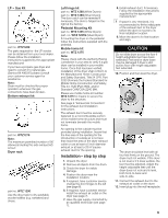
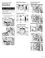
2 1 3 1 ć Exhaust air outlet on the rear of the appliance (standard) 2 ć Exhaust air outlet on the side (optional) 3 ć Exhaust air outlet on the underside of the appliance (optional) Special exhaust air connections must be obtained from our customer service for either connection type (see page 8). - Side air exhaust - Bottom air exhaust A qualified technician should change the exhaust air outlet to the optional connection location. Ductwork To ensure optimum performance, the ducting system of the dryer should be as short as possible with a minimum number of elbows. Your dryer will work best when the venting system has as few air flow restrictions as possible. Exhaust ducting which is longer than recommended may extend drying time, cause lint to accumulate and affect dryer performance and dryer life. FourĆinch (approx. 100 mm) diameter ducting should be used. Use either rigid metal or flexible metal ducting material. DO NOT use plastic or nonĆmetal duct with this dryer. DO NOT assemble the ductwork with screws or fasteners that extend into the duct. They will serve as an accumulation point for lint. Joints should be secured with aluminium tape. All joints should be tight to avoid leaks. The male end of each duct section must point away from the dryer. Whether connecting to an existing venting system or a new venting system, make sure that all ducting is clean and free of lint. The maximum permitted length for both rigid and flexible metal duct is shown in the table below. Number of 90° Turns or Elbows 0 1 2 3 4 Rigid Duct 66 ft. (2011 cm) 56 ft. (1707 cm) 48 ft. (1463 cm) 39 ft. (1189 cm) 30 ft. (914 cm) Flexible Duct 45 ft. (1372 cm) 36 ft. (1097 cm) 29 ft. (884 cm) 22 ft. (671 cm) 16 ft. (488 cm) Note: Side and bottom exhaust installations have a 90° turn inside the dryer. To determine maximum exhaust length, add one 90° turn to the chart. More than two 90° turns are not recommended. For best performance, separate all turns by at least 4 ft. of straight duct, including distance between last turn and exhaust hood. Exhaust vent hood The exhaust duct must end with an approved exhaust vent hood with swing out damper(s). DO NOT use an exhaust vent hood with magnetic latches. To avoid exhaust restriction, the outlet must be a minimum of 12 inches (30 cm) above ground level or any other obstructing surface. Required parts The parts required for the exhaust air system (elbows, lines, exhaust air outlets) are not included in standard delivery of the dryer. Accessories The parts required for the exhaust air system can be obtained from customer service or your local dealer. Please follow the installation instructions supplied by the appropriate manufacturer! Side exhaust kit part no. WTZ 1265 Note: The maximum permitted number of 90° elbows (including this side exhaust kit) is four! i Special tool for cutting the hole in prepared side panel is required. Contact local dealer! 8
-
 1
1 -
2
-
 3
3 -
 4
4 -
 5
5 -
 6
6 -
 7
7 -
 8
8 -
 9
9 -
 10
10 -
 11
11 -
 12
12 -
 13
13 -
14
-
15
-
16
-
17
-
18
-
19
-
20
-
21
-
22
-
23
-
24
-
25
-
26
-
27
-
28
-
29
-
30
-
31
-
32
-
33
-
34
-
35
-
36
-
37
-
38
-
39
-
40
-
41
-
42
-
43
-
44
-
45
-
46
-
47
-
48
-
49
-
50
-
51
-
52
-
53
-
54
-
55
-
56
-
57
-
58
-
59
-
60
-
61
-
62
-
63
-
64
-
65
-
66
-
67
-
68
 |
 |