Bowflex Blaze Assembly Manual - Page 17
Step 16 - Attach the Upper Lat Tower to the Lower, Step 17 - Attach the Rod Box with Power Rod® unit
 |
View all Bowflex Blaze manuals
Add to My Manuals
Save this manual to your list of manuals |
Page 17 highlights
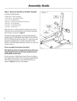
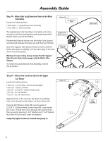
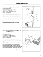
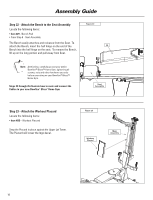
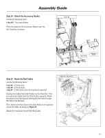
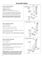
Assembly Guide Step 16 - Attach the Upper Lat Tower to the Lower Locate the following items: • From Step 15 - Upper Lat Tower Assembly • From Step 14 - Main Assembly • Item #E - (6) 3/8" X 3/4" Button Head Screw • Item #N - (6) 3/8" Washers Carefully insert the end of the Upper Lat Tower into the open end of the Lower Lat Tower. Align the holes on the Upper Lat Tower with the holes on the Lower Lat Tower. Place (6) 3/8" Washers (Item #N) over the ends of (6) 3/8" X 3/4" Button Head Screws (Item #E) - one washer per screw. Thread the screws into the aligned holes, as shown in Figure 16. Completely tighten hardware installed during Step 16. Figure 16 Upper Lat Tower N E Lower Lat Tower Step 17 - Attach the Rod Box with Power Rod® unit to the Rod Box Frame Locate the following items: Figure 17 • Item #24 - Rod Box Frame • Item #25 - Rod Box with Power Rod® unit • Item #B - (3) #10 X 1" Phillips Head Screws • Item #L - (3) 1/4" Washers Place the Rod Box Frame (Item #24) and Rod Box with Power Rod® unit (Item #25) onto one side as shown in Figure 17. Slide the Rod Box with Power Rod® unit into the Rod Box Frame until the Rod Box is completely seated in the Rod Box Frame. 24 Slot 25 Place (3) 1/4" Washers (Item #L) over the ends of (3) #10 X 1" Phillips Head Screws (Item #B) - one washer per screw. Insert the screws through the slot on the Rod Box Frame and thread into the holes in the Rod Box with Power Rod® unit. L B Completely tighten hardware installed during Step 17. 15
-
 1
1 -
2
-
3
-
4
-
5
-
6
-
7
-
8
-
9
-
10
-
11
-
 12
12 -
 13
13 -
 14
14 -
 15
15 -
 16
16 -
 17
17 -
 18
18 -
 19
19 -
 20
20 -
 21
21 -
 22
22 -
23
-
24
 |
 |
