Bowflex Blaze Assembly Manual - Page 9
Step 4 - Attach the Chest Bar with Pulleys to the, Main Assembly, Step 5 - Attach the Seat Bracket
 |
View all Bowflex Blaze manuals
Add to My Manuals
Save this manual to your list of manuals |
Page 9 highlights
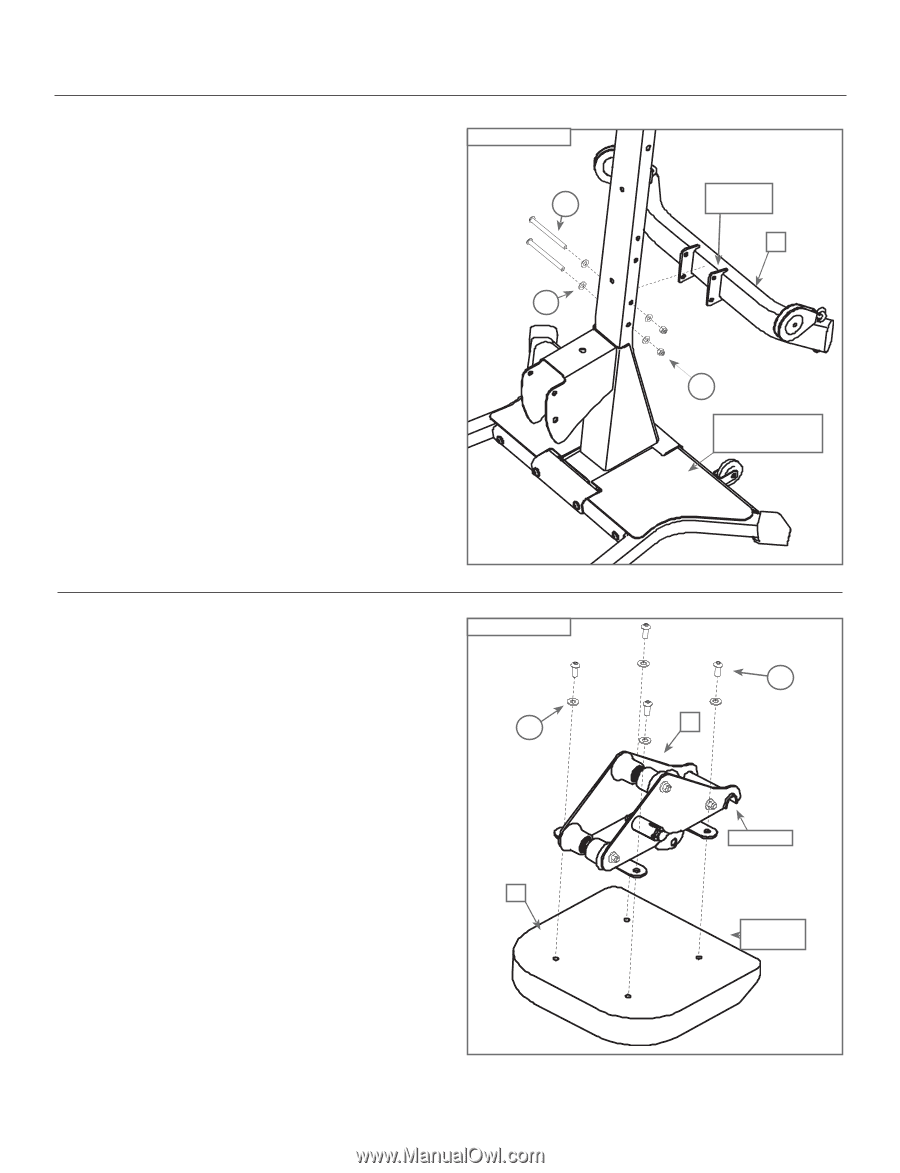
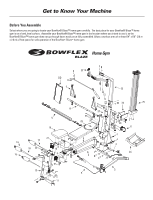
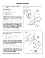
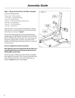
Assembly Guide Step 4 - Attach the Chest Bar with Pulleys to the Main Assembly Locate the following items: • From Step 3 - Main Assembly • Item #6 - Chest Bar w/ Pulleys - Do not unwrap cables! • Item #K - (2) 3/8" X 5" Button Head Screws • Item #N - (4) 3/8" Washers • Item #O - (2) 3/8" Nylock Nuts Line up the bolt holes in the brackets on the Chest Bar with Pulleys (Item #6) with the lowest bolt holes on the Lower Lat Tower, as shown in Figure 4. Pulleys should be oriented forward. Place (2) 3/8" Washers (Item #N) over the end of (2) 3/8" X 5" Button Head Screws (Item #K) - one washer per screw. Insert the screws through the lined up holes in the Chest Bar with Pulleys and the Lower Lat Tower, and secure each screw by placing (1) 3/8" Washers and (1) 3/8" Nylock Nuts (Item #O) over the end of each screw. Completely tighten hardware installed during Step 4. Figure 4 K N Step 5 - Attach the Seat Bracket to the Seat Pad Locate the following items: • Item #7 - Seat Pad • Item #8 - Seat Bracket • Item #C - (4) 5/16" X 3/4" Button Head Screws • Item #M - (4) 5/16" Washers Place the Seat Pad (Item #7) on the floor, cushion-side down. Position the Seat Bracket (Item #8) so the cut-out is toward the angled edge of the Seat Pad. Align the four holes in the Seat Bracket with the four holes in the Seat Pad. Place (4) 5/16" Washers (Item #M) over (4) 5/16" X 3/4" Button Head Screws (Item #C) - one over each screw, and use those screws to secure the Seat Bracket to the Seat Pad. Completely tighten hardware installed during Step 5. Figure 5 M 7 Chest Bar Brackets 6 O Base Platform/ Lower Lat Tower Assembly C 8 Cut-out Angled Edge 7
-
 1
1 -
2
-
3
-
 4
4 -
 5
5 -
 6
6 -
 7
7 -
 8
8 -
 9
9 -
 10
10 -
 11
11 -
 12
12 -
 13
13 -
 14
14 -
15
-
16
-
17
-
18
-
19
-
20
-
21
-
22
-
23
-
24
 |
 |