Brother International HL 1030 Service Manual - Page 93
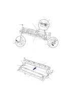
heat roller with the four hooks on the fixing unit frame.
 |
UPC - 012502020134
View all Brother International HL 1030 manuals
Add to My Manuals
Save this manual to your list of manuals |
Page 93 highlights
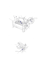
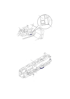
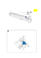
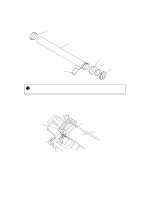
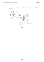
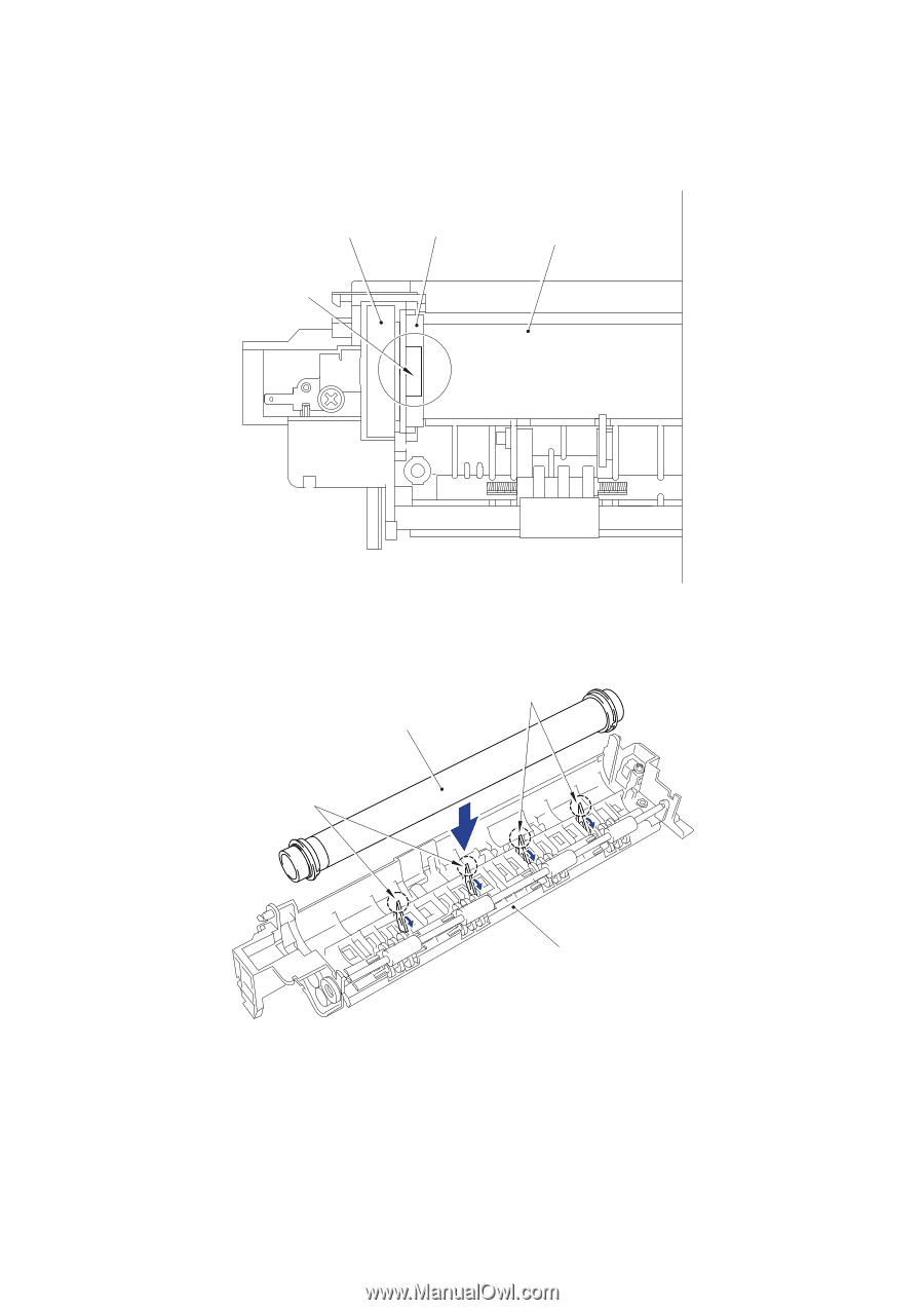
CHAPTER 4 DISASSEMBLY AND RE-ASSEMBLY • When re-assembling the heat roller bearing which is assembled at the heat roller gear side, fix the bearing onto the heat roller so that the embossment whose thickness is 0.5mm is at the top. Heat roller gear Heat roller bearing Heat roller (embossment) Fig. 4-41 • When re-assembling the heat roller to the fixing unit frame, ensure you do not damage the heat roller with the four hooks on the fixing unit frame. Heat roller (hooks) (hooks) Fixing unit frame Fig. 4-42 4-23
-
 1
1 -
2
-
3
-
4
-
5
-
6
-
7
-
8
-
9
-
10
-
11
-
12
-
13
-
14
-
15
-
16
-
17
-
18
-
19
-
20
-
21
-
22
-
23
-
24
-
25
-
26
-
27
-
28
-
29
-
30
-
31
-
32
-
33
-
34
-
35
-
36
-
37
-
38
-
39
-
40
-
41
-
42
-
43
-
44
-
45
-
46
-
47
-
48
-
49
-
50
-
51
-
52
-
53
-
54
-
55
-
56
-
57
-
58
-
59
-
60
-
61
-
62
-
63
-
64
-
65
-
66
-
67
-
68
-
69
-
70
-
71
-
72
-
73
-
74
-
75
-
76
-
77
-
78
-
79
-
80
-
81
-
82
-
83
-
84
-
85
-
86
-
87
-
 88
88 -
 89
89 -
 90
90 -
 91
91 -
 92
92 -
 93
93 -
 94
94 -
 95
95 -
 96
96 -
 97
97 -
 98
98 -
99
-
100
-
101
-
102
-
103
-
104
-
105
-
106
-
107
-
108
-
109
-
110
-
111
-
112
-
113
-
114
-
115
-
116
-
117
-
118
-
119
-
120
-
121
-
122
-
123
-
124
-
125
-
126
-
127
-
128
-
129
-
130
-
131
-
132
-
133
-
134
-
135
-
136
-
137
-
138
-
139
-
140
-
141
-
142
-
143
-
144
-
145
-
146
-
147
-
148
-
149
-
150
-
151
-
152
-
153
-
154
-
155
-
156
-
157
-
158
-
159
-
160
-
161
-
162
-
163
-
164
-
165
-
166
-
167
-
168
-
169
-
170
-
171
-
172
-
173
-
174
-
175
-
176
-
177
-
178
-
179
-
180
-
181
-
182
-
183
-
184
-
185
-
186
-
187
-
188
-
189
-
190
-
191
-
192
-
193
-
194
-
195
-
196
-
197
-
198
-
199
-
200
-
201
-
202
-
203
-
204
-
205
-
206
-
207
-
208
-
209
-
210
-
211
-
212
-
213
-
214
-
215
-
216
-
217
-
218
-
219
-
220
-
221
-
222
-
223
-
224
-
225
-
226
-
227
-
228
-
229
-
230
-
231
-
232
-
233
-
234
-
235
-
236
-
237
-
238
-
239
-
240
-
241
-
242
-
243
 |
 |
CHAPTER 4
DISASSEMBLY AND RE-ASSEMBLY
4-23
•
When re-assembling the heat roller bearing which is assembled at the heat roller gear side,
fix the bearing onto the heat roller so that the embossment whose thickness is 0.5mm is at
the top.
Fig. 4-41
•
When re-assembling the heat roller to the fixing unit frame, ensure you do not damage the
heat roller with the four hooks on the fixing unit frame.
Fig. 4-42
Heat roller
Heat roller
Fixing unit frame
Heat roller bearing
(hooks)
(embossment)
(hooks)
Heat roller gear