Brother International HL 1030 Service Manual - Page 99
Base Plate, Slide the base plate to the rear of the printer to remove it.
 |
UPC - 012502020134
View all Brother International HL 1030 manuals
Add to My Manuals
Save this manual to your list of manuals |
Page 99 highlights
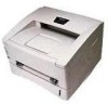
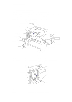
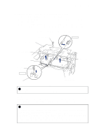
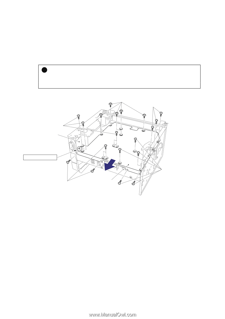
CHAPTER 4 DISASSEMBLY AND RE-ASSEMBLY 3.11 Base Plate (1) Turn the main frame upside down. (2) Remove the five M4x10 Taptite screws and 16 (sixteen) M3x8 Taptite screws from the base plate. (3) Slide the base plate to the rear of the printer to remove it. ! CAUTION: Do not remove the ground wire connected to the base plate if it is not necessary to remove the low-voltage power supply unit. Unnecessary disconnection of the ground wire may cause increased printer noise. Taptite, bind M4x10 Taptite, bind M3x8 Taptite, bind M3x8 Main frame Ground wire connection Taptite, bind M3x8 Base plate Fig. 4-48 Taptite, bind M3x8 4-27
-
 1
1 -
2
-
3
-
4
-
5
-
6
-
7
-
8
-
9
-
10
-
11
-
12
-
13
-
14
-
15
-
16
-
17
-
18
-
19
-
20
-
21
-
22
-
23
-
24
-
25
-
26
-
27
-
28
-
29
-
30
-
31
-
32
-
33
-
34
-
35
-
36
-
37
-
38
-
39
-
40
-
41
-
42
-
43
-
44
-
45
-
46
-
47
-
48
-
49
-
50
-
51
-
52
-
53
-
54
-
55
-
56
-
57
-
58
-
59
-
60
-
61
-
62
-
63
-
64
-
65
-
66
-
67
-
68
-
69
-
70
-
71
-
72
-
73
-
74
-
75
-
76
-
77
-
78
-
79
-
80
-
81
-
82
-
83
-
84
-
85
-
86
-
87
-
88
-
89
-
90
-
91
-
92
-
93
-
 94
94 -
 95
95 -
 96
96 -
 97
97 -
 98
98 -
 99
99 -
 100
100 -
 101
101 -
 102
102 -
 103
103 -
 104
104 -
105
-
106
-
107
-
108
-
109
-
110
-
111
-
112
-
113
-
114
-
115
-
116
-
117
-
118
-
119
-
120
-
121
-
122
-
123
-
124
-
125
-
126
-
127
-
128
-
129
-
130
-
131
-
132
-
133
-
134
-
135
-
136
-
137
-
138
-
139
-
140
-
141
-
142
-
143
-
144
-
145
-
146
-
147
-
148
-
149
-
150
-
151
-
152
-
153
-
154
-
155
-
156
-
157
-
158
-
159
-
160
-
161
-
162
-
163
-
164
-
165
-
166
-
167
-
168
-
169
-
170
-
171
-
172
-
173
-
174
-
175
-
176
-
177
-
178
-
179
-
180
-
181
-
182
-
183
-
184
-
185
-
186
-
187
-
188
-
189
-
190
-
191
-
192
-
193
-
194
-
195
-
196
-
197
-
198
-
199
-
200
-
201
-
202
-
203
-
204
-
205
-
206
-
207
-
208
-
209
-
210
-
211
-
212
-
213
-
214
-
215
-
216
-
217
-
218
-
219
-
220
-
221
-
222
-
223
-
224
-
225
-
226
-
227
-
228
-
229
-
230
-
231
-
232
-
233
-
234
-
235
-
236
-
237
-
238
-
239
-
240
-
241
-
242
-
243
 |
 |
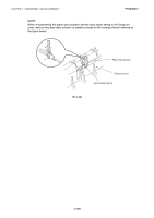
CHAPTER 4
DISASSEMBLY AND RE-ASSEMBLY
4-27
3.11
Base Plate
(1) Turn the main frame upside down.
(2)
Remove the five M4x10 Taptite screws and 16 (sixteen) M3x8 Taptite screws from the
base plate.
(3)
Slide the base plate to the rear of the printer to remove it.
!
CAUTION:
Do not remove the ground wire connected to the base plate if it is not necessary to remove the
low-voltage power supply unit.
Unnecessary disconnection of the ground wire may cause
increased printer noise.
Fig. 4-48
Taptite, bind M4x10
Taptite, bind M3x8
Taptite, bind M3x8
Taptite, bind M3x8
Taptite, bind M3x8
Base plate
Main frame
Ground wire connection