Brother International HS-5300 Service Manual - Page 30
Engine, Driver, FAN_HIGH, Motor, ASIC3, C_FAN
 |
View all Brother International HS-5300 manuals
Add to My Manuals
Save this manual to your list of manuals |
Page 30 highlights
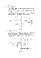
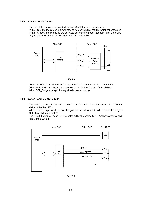
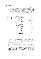
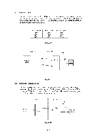
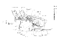
1.4.7 Fan Drive Circuit The fan drive circuit controls the rotation speed of the fan motor. The fan can rotate at high speed, low speed or stopped by the combination of the FAN_HIGH and FAN_LOW signals output from the engine CPU. The relationship between the signals and rotation speed are shown in the table below. FAN _ HIGH High Low Low FAN _ LOW Low High Low Rotation speed High Low Stop Fig. 2.10 Main PCB i Driver PCB +25V 0 Engine CPU FAN_HIGH FAN LOW Driver P6 Fan Motor Fig. 2.11 1.4.8 PS Fan Motor Drive Circuit The PS fan motor drive circuit controls the rotation of PS fan motor to cool down the power supply unit. It is controlled by the C_FAN signal output through the Jet ASIC3 from the engine CPU which controls the fan rotation and stop. The motor starts rotating when the signal is high and stops when the signal is low. Engine CPU Main PCB i 0. Jet C_FAN ASIC3 Driver PCB +25V 0 P19 Driver PS Fan Motor Fig. 2.12
-
 1
1 -
2
-
3
-
4
-
5
-
6
-
7
-
8
-
9
-
10
-
11
-
12
-
13
-
14
-
15
-
16
-
17
-
18
-
19
-
20
-
21
-
22
-
23
-
24
-
 25
25 -
 26
26 -
 27
27 -
 28
28 -
 29
29 -
 30
30 -
 31
31 -
 32
32 -
 33
33 -
 34
34 -
 35
35 -
36
-
37
-
38
-
39
-
40
-
41
-
42
-
43
-
44
-
45
-
46
-
47
-
48
-
49
-
50
-
51
-
52
-
53
-
54
-
55
-
56
-
57
-
58
-
59
-
60
-
61
-
62
-
63
-
64
-
65
-
66
-
67
-
68
-
69
-
70
-
71
-
72
-
73
-
74
-
75
-
76
-
77
-
78
-
79
-
80
-
81
-
82
-
83
-
84
-
85
-
86
-
87
-
88
-
89
-
90
-
91
-
92
-
93
-
94
-
95
-
96
-
97
-
98
-
99
-
100
-
101
-
102
-
103
-
104
-
105
-
106
-
107
-
108
-
109
-
110
-
111
-
112
-
113
-
114
-
115
-
116
-
117
-
118
-
119
-
120
-
121
-
122
-
123
-
124
-
125
-
126
-
127
-
128
-
129
-
130
-
131
-
132
-
133
-
134
-
135
-
136
-
137
-
138
-
139
-
140
-
141
-
142
-
143
-
144
-
145
-
146
-
147
-
148
-
149
-
150
-
151
-
152
-
153
-
154
-
155
-
156
-
157
-
158
-
159
-
160
-
161
-
162
-
163
-
164
-
165
-
166
-
167
-
168
 |
 |