Brother International HS-5300 Service Manual - Page 66
<Disassembly>
 |
View all Brother International HS-5300 manuals
Add to My Manuals
Save this manual to your list of manuals |
Page 66 highlights
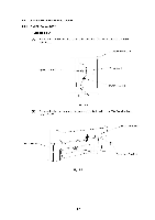
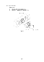
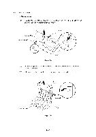
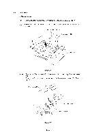
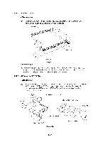
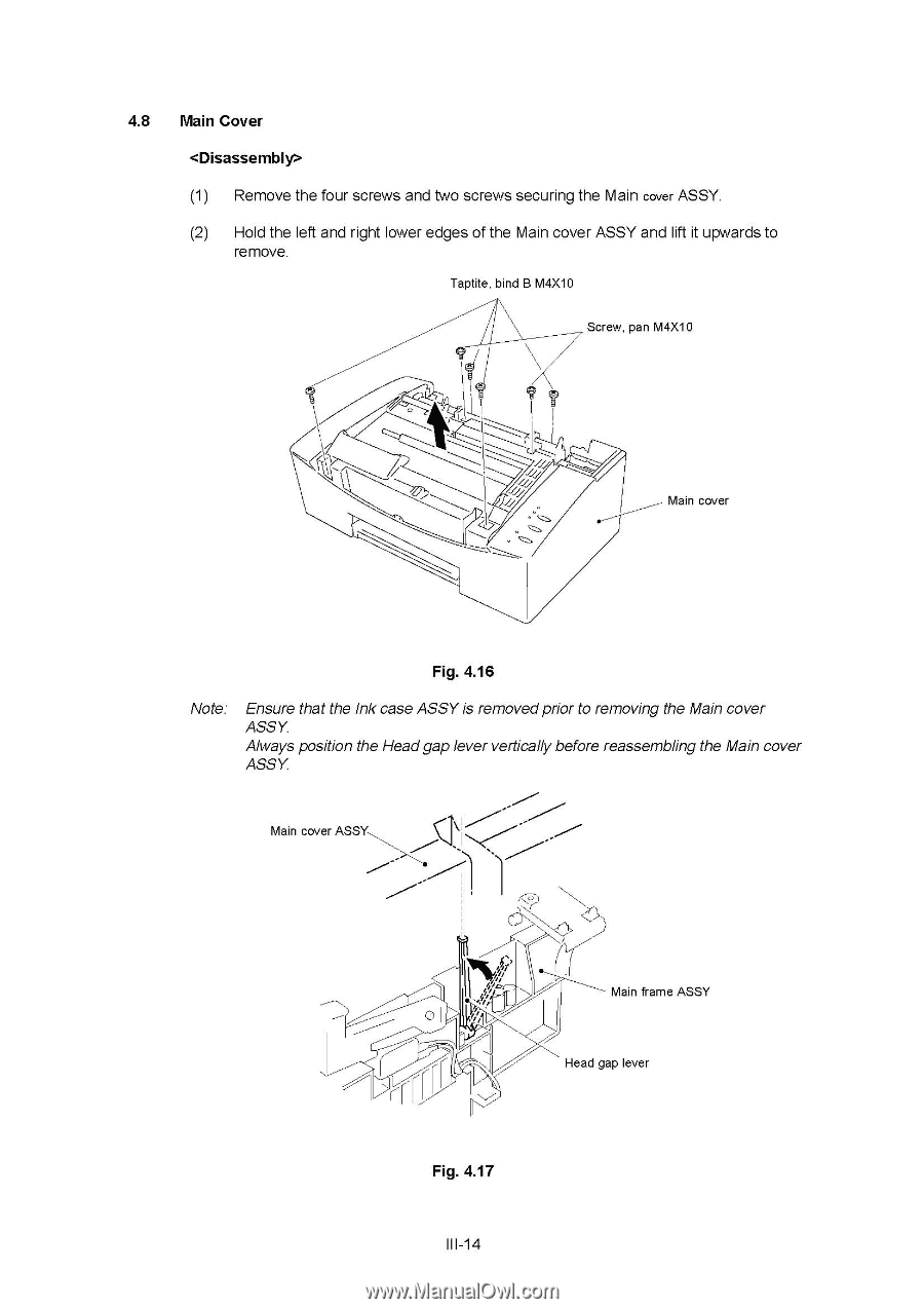
4.8 Main Cover (1) Remove the four screws and two screws securing the Main cover ASSY. (2) Hold the left and right lower edges of the Main cover ASSY and lift it upwards to remove. Taptite, bind B M4X10 Screw, pan M4X10 Main cover Fig. 4.16 Note: Ensure that the Ink case ASSY is removed prior to removing the Main cover ASSY. Always position the Head gap lever vertically before reassembling the Main cover ASSY. Main cover ASSY rr Fig. 4.17 III-14 Main frame ASSY Head gap lever
-
 1
1 -
2
-
3
-
4
-
5
-
6
-
7
-
8
-
9
-
10
-
11
-
12
-
13
-
14
-
15
-
16
-
17
-
18
-
19
-
20
-
21
-
22
-
23
-
24
-
25
-
26
-
27
-
28
-
29
-
30
-
31
-
32
-
33
-
34
-
35
-
36
-
37
-
38
-
39
-
40
-
41
-
42
-
43
-
44
-
45
-
46
-
47
-
48
-
49
-
50
-
51
-
52
-
53
-
54
-
55
-
56
-
57
-
58
-
59
-
60
-
 61
61 -
 62
62 -
 63
63 -
 64
64 -
 65
65 -
 66
66 -
 67
67 -
 68
68 -
 69
69 -
 70
70 -
 71
71 -
72
-
73
-
74
-
75
-
76
-
77
-
78
-
79
-
80
-
81
-
82
-
83
-
84
-
85
-
86
-
87
-
88
-
89
-
90
-
91
-
92
-
93
-
94
-
95
-
96
-
97
-
98
-
99
-
100
-
101
-
102
-
103
-
104
-
105
-
106
-
107
-
108
-
109
-
110
-
111
-
112
-
113
-
114
-
115
-
116
-
117
-
118
-
119
-
120
-
121
-
122
-
123
-
124
-
125
-
126
-
127
-
128
-
129
-
130
-
131
-
132
-
133
-
134
-
135
-
136
-
137
-
138
-
139
-
140
-
141
-
142
-
143
-
144
-
145
-
146
-
147
-
148
-
149
-
150
-
151
-
152
-
153
-
154
-
155
-
156
-
157
-
158
-
159
-
160
-
161
-
162
-
163
-
164
-
165
-
166
-
167
-
168
 |
 |
4.8
Main
Cover
<Disassembly>
(1)
Remove
the
four
screws
and
two
screws
securing
the
Main
cover
ASSY.
(2)
Hold
the
left
and
right
lower
edges
of
the
Main
cover
ASSY
and
lift
it
upwards
to
remove.
Taptite,
bind
B
M4X10
Screw,
pan
M4X10
Main
cover
Fig.
4.16
Note:
Ensure
that
the
Ink
case
ASSY
is
removed
prior
to
removing
the
Main
cover
ASSY.
Always
position
the
Head
gap
lever
vertically
before
reassembling
the
Main
cover
ASSY.
Main
cover
ASSY
Main
frame
ASSY
Head
gap
lever
rr
Fig.
4.17
III
-14