Brother International HS-5300 Service Manual - Page 76
approximately
 |
View all Brother International HS-5300 manuals
Add to My Manuals
Save this manual to your list of manuals |
Page 76 highlights
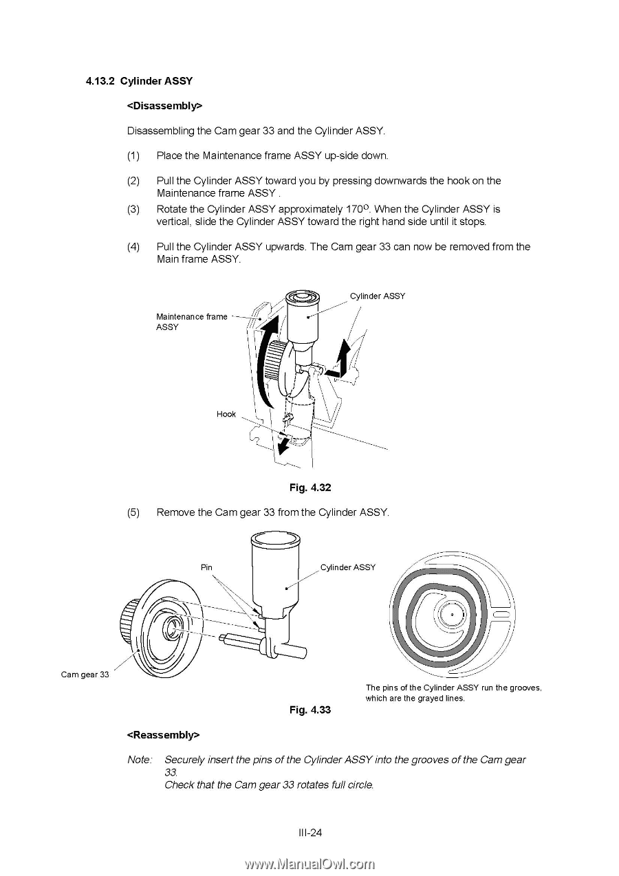
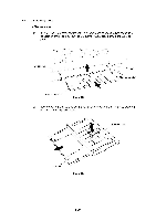
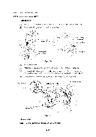
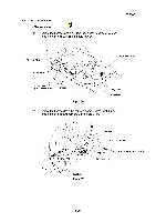
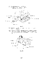
4.13.2 Cylinder ASSY Disassembling the Cam gear 33 and the Cylinder ASSY. (1) Place the Maintenance frame ASSY up-side down. (2) Pull the Cylinder ASSY toward you by pressing downwards the hook on the Maintenance frame ASSY . (3) Rotate the Cylinder ASSY approximately 170°. When the Cylinder ASSY is vertical, slide the Cylinder ASSY toward the right hand side until it stops. (4) Pull the Cylinder ASSY upwards. The Cam gear 33 can now be removed from the Main frame ASSY. Maintenance frame ASSY Cylinder ASSY r( Hook Fig. 4.32 (5) Remove the Cam gear 33 from the Cylinder ASSY. Pin Cylinder ASSY Cam gear 33 Fig. 4.33 The pins of the Cylinder ASSY run the grooves, which are the grayed lines. Note: Securely insert the pins of the Cylinder ASSY into the grooves of the Cam gear 33. Check that the Cam gear 33 rotates full circle. III-24
-
 1
1 -
2
-
3
-
4
-
5
-
6
-
7
-
8
-
9
-
10
-
11
-
12
-
13
-
14
-
15
-
16
-
17
-
18
-
19
-
20
-
21
-
22
-
23
-
24
-
25
-
26
-
27
-
28
-
29
-
30
-
31
-
32
-
33
-
34
-
35
-
36
-
37
-
38
-
39
-
40
-
41
-
42
-
43
-
44
-
45
-
46
-
47
-
48
-
49
-
50
-
51
-
52
-
53
-
54
-
55
-
56
-
57
-
58
-
59
-
60
-
61
-
62
-
63
-
64
-
65
-
66
-
67
-
68
-
69
-
70
-
 71
71 -
 72
72 -
 73
73 -
 74
74 -
 75
75 -
 76
76 -
 77
77 -
 78
78 -
 79
79 -
 80
80 -
 81
81 -
82
-
83
-
84
-
85
-
86
-
87
-
88
-
89
-
90
-
91
-
92
-
93
-
94
-
95
-
96
-
97
-
98
-
99
-
100
-
101
-
102
-
103
-
104
-
105
-
106
-
107
-
108
-
109
-
110
-
111
-
112
-
113
-
114
-
115
-
116
-
117
-
118
-
119
-
120
-
121
-
122
-
123
-
124
-
125
-
126
-
127
-
128
-
129
-
130
-
131
-
132
-
133
-
134
-
135
-
136
-
137
-
138
-
139
-
140
-
141
-
142
-
143
-
144
-
145
-
146
-
147
-
148
-
149
-
150
-
151
-
152
-
153
-
154
-
155
-
156
-
157
-
158
-
159
-
160
-
161
-
162
-
163
-
164
-
165
-
166
-
167
-
168
 |
 |