Brother International LT2-B875 MKII Instruction Manual - Multi - Page 31
Installing, Installation, courroie, Riemenmontage, Instalacion, correa, bobbin, winder, bobineur,
 |
View all Brother International LT2-B875 MKII manuals
Add to My Manuals
Save this manual to your list of manuals |
Page 31 highlights
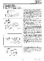
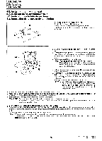
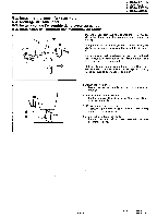
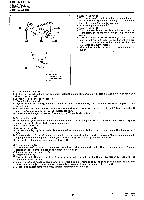
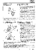
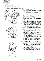
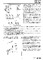
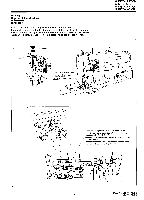
5. INSTALLATION 5. MONTAGE 5. INSTALLATION 5. INSTALACION 5-4. Installing the belt 5-4. Riemenmontage 5-4. Installation de la .courroie 5-4. Instalacion de la correa 1. Tilt back the machine head, and then place the belt 0 onto the motor pulley and the machine pulley. 2. Turn the nut 0 to adjust so that there is 10-20 mm of deflection in the belt 0 when it is pressed with a finger with a force of 9.8 N (1 kgf). 10-20mm 1. Klappen Sie das Maschinenoberteil zur0ck und bringen Sie den Riemen 0 an der Riemenscheibe des Motors und der Nahmaschine an. 2. Stellen Sie die Riemenspannung mit der Mutter 0 ein, so dell der Riemen urn 10 bis 20 mm eingedruckt wird, wenn er mit einer Kraft von 9,8 N (1 kg) gedrtickt wird. a O 8 1. Incliner la tete de machine vers l'arriere, puis placer la courroie 0 sur la poulie de moteur et sur la poulie de machine. 2. Tourner l'ecrou 0 pour regler de maniere que la courroie 0 s'enfonce de 10-20 mm lorsqu'on appuie sur la courroie avec un doigt avec une force de 9,8 N (1 kgf). 1. lnclinar la cabeza de la maquina hacia atras, y luego colocar la coorea 0 sobre la polea del motor y la polea de la maquina. 2. Girar la tuerca 0 para ajustar de manera que la correa 0 tenga una deflexion de 10-20 mm al presionarla con un dedo haciendo una fuerza de 9,8 N (1 kgf). 5-5. Installing the bobbin winder 5-5. Installation du bobineur de canette 5-5. Montage des Spulers 5-5. Instalacion de la bobinadora 5 mm 1. Push down the bobbin presser arm 0 as far as it will go. 2. Place the bobbin winder wheel 0 so that it pushes the 0 belt 0 by approximately 5 mm, and then place the bobbin winder 0 so that it is parallel with the belt hole in the work table. 3. Install the bobbin winder 0 to the work table with the two screws 0. 4. Pull the bobbin presser arm 0 back and check that there is approximately 8 mm of clearance between the bob- bin winder wheel 0 and the belt 0. 0 1. Drucken Sie den Spulenarm 0 so weit wie moglich nach unten. 2. Positionieren Sie das Spulerrad 0, so daB der Riemen 0 um ungefahr 5 mm eingedruckt wird und richten Sie den Spuler 0 parallel zur Riemenoffnung im Nahtisch aus. 3. Befestigen Sie den Spuler 0 mit den beiden Schrauben 0 am Nahtisch. 0 0 4. Ziehen Sie den Spulenarm 0 zur0ck und kontrollieren 8 mm O O Sie, ob der Abstand zwischen dem Spulerrad 0 und dem Riemen 0 ungefahr 8 mm betragt. 1. Abaisser au maximum le bras 0 du presseur de canette. 0 2. Placer Ia roue 0 du bobineur de canette de maniere qu'elle pousse la courroie 0 d'environ 5 mm, puis placer le bobineur de canette 0 parallelement au trou de courroie dans la table de travail. 3. Installer le bobineur de canette 0 sur la table de travail a l'aide des deux vis 0. 4. Tirer le bras 0 du presseur de canette vers l'arriere et verifier qu'il y ait un ecart d'environ 8 mm entre la roue 0 du bobineur de canette et la courroie 0. 1. Empujar hacia abajo tanto como sea posible el brazo presionador de la bobina 0. 2. Colocar Ia rueda de la bobinadora 0 de manera que empuje la correa 0 aproximadamente 5 mm, y luego colocar la bobinadora 0 de manera que quede paralela con el orificio de la correa en la mesa de trabajo. 3. Instalar la bobinadora 0 en la mesa de trabajo con los dos tornillos 0. 4. Tirar del brazo presionador de la bobina 0 hacia atras y verificar que exists una separacien de aproximadamente 8 mm entre la rueda de la bobinadora 0 y la correa 0. - 16 - Model No. LT2-8840 Mark II LT2-B870 Mark II
-
 1
1 -
2
-
3
-
4
-
5
-
6
-
7
-
8
-
9
-
10
-
11
-
12
-
13
-
14
-
15
-
16
-
17
-
18
-
19
-
20
-
21
-
22
-
23
-
24
-
25
-
 26
26 -
 27
27 -
 28
28 -
 29
29 -
 30
30 -
 31
31 -
 32
32 -
 33
33 -
 34
34 -
 35
35 -
 36
36 -
37
-
38
-
39
-
40
-
41
-
42
-
43
-
44
-
45
-
46
-
47
-
48
-
49
-
50
-
51
-
52
-
53
-
54
-
55
-
56
-
57
-
58
-
59
-
60
-
61
-
62
-
63
-
64
-
65
-
66
-
67
-
68
-
69
-
70
-
71
-
72
-
73
-
74
-
75
-
76
-
77
-
78
-
79
-
80
-
81
-
82
-
83
-
84
-
85
-
86
-
87
-
88
-
89
-
90
-
91
-
92
-
93
-
94
-
95
-
96
-
97
-
98
 |
 |
