Brother International LT2-B875 MKII Instruction Manual - Multi - Page 73
Standard, Adjustments, Standardeinstellungen, Reglages, Ajustes, Estandares, Remove, Needle, Plate
 |
View all Brother International LT2-B875 MKII manuals
Add to My Manuals
Save this manual to your list of manuals |
Page 73 highlights
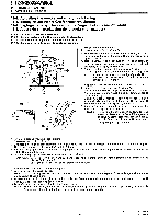
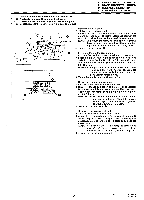
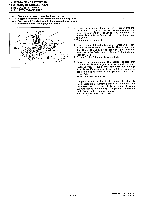
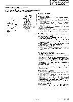
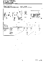
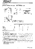
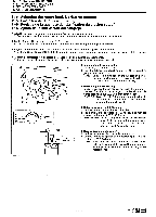
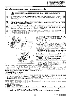
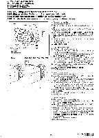
11. STANDARD ADJUSTMENTS 11. STANDARDEINSTELLUNGEN 11. REGLAGES STANDARD 11. AJUSTES ESTANDARES 7. Remove the needle plate. 8. Remove the feed dog. 9. Set the stitch length to either 2 (approx. 2 mm) or 3 (approx. 3 mm► on the scale, depending on the model and e specifications of the machine. (Refer to the table.) 10. Turn the machine pulley to raise the needle bar by H mm from its lowest position (refer to the table below for the e ®. value for H). 11. The reference line 6 on the needle bar will be aligned with the lower edge of the needle bar supporter ® The rotary hook tip must be aligned with the center of the needle at this time. 12. Tilt back the machine head, loosen the three screws 0, and then align the rotary hook tip with the center of the 0. needle. 13. Tighten the screws 14. The distance from the upper edge of the needle hole to the rotary hook tip (I) must be 1-1.5 mm when the rotary hook tip 41) is aligned with the center of the needle. 15. Install the feed dog. 16. Install the needle plate. 7. Entfernen Sie die Stichplatte. 8. "Entfernen Sie den Transporteur. 9. Stellen Sie die Stichlange je nach dem Modell und der Ausfuhrung der Maschine auf der Skala auf 2 (2 mm) bzw. 3 ® (3 mm) ein. (Siehe Tabelle.) 10. Drehen Sie die Riemenscheibe, um die Nadelstange von der untersten Position um H mm hochzustellen. (Siehe ® e Tabelle fur den Wert H.) 11. Richten Sie die Bezugslinie C) auf der Nadelstange auf die untere Kante der Nadelstangenhalterung aus. Die Greiferspitze mu( dabei auf die Nadelmitte ausgerichtet sein. ® 12. Klappen Sie das Maschienenoberteil nach hinten zurOck, losen Sie die drei Schrauben e Greiferspitze auf die Nadelmitte aus. und richten Sie die 13. Ziehen Sie die Schrauben m wieder fest. ® 14. Der Abstand zwischen der oberen Kante des Nadellochs und der Greiferspitze e Greiferspitze auf die Nadelmitte ausgerichtet ist. mu( 1-1,5 mm betragen, wenn die 15. Bauen Sie den Transporteur wieder ein. 16. Bringen Sie die Stichplatte wieder an. 7. Retirer Ia plaque a aiguille. 8. Retirer la griffe d'entrainement. 9. Regler la longueur de point a 2 (environ 2 mm) ou a 3 (environ 3 mm) sur l'echelle, en fonction du modele et des specifications de la machine. (Se reporter au tableau.) 10. Tourner la poulie de machine de maniere a elever la barre a aiguille 0 de H mm a partir de sa position la plus e basse. (Se reporter au tableau ci-dessous pour ce qui concerne la valeur de H.) 11. Aligner la ligne de reference 6 marquee sur la barre a aiguille avec le bord inferieur du support de la barre e aiguille. A ce moment, l'extremite du crochet rotatif doit etre alignee avec le centre de l'aiguille. 12. Incliner la tete de machine vers l'arriere, desserrer les trois vis m, puis aligner l'extrernite du crochet rotatif ID avec le centre de l'aiguille. 13. Serrer les vis e 14. L'ecart entre le cote superieur de ('orifice d'aliguille et l'extremite du crochet rotatif doit etre de 1-1,5 mm lorsque l'extrernite du crochet rotatif est alignee avec le centre de l'aiguille. 15. Installer la grille d'entrainement. 16. Installer la plaque a aiguille. 7. Quitar la place de agujas. 8. Desmontar el alimentador. 9. Ajustar el largo de puntada a 2 (aprox. 2 mm) o 3 (aprox. 3 mm) en la escala, dependiendo del modelo y especificaciones de la maquina. (Consulter el cuadro.) 10. Girar la polea de la maquina para levantar 1a barra de agujas H mm de su posici6n mas baja (consultar el cuadro e a continuaci6n por el valor de H.) 11. Alinear Ia lima de referencia 6 en la barra de agujas con el borde inferior del soporte de la barra de agujas La punta del cangrejo debe estar alineada al mismo tiempo con el centro de la guja. 12. Incliner hacia atras la cabeza de la maquina, aflojar los tres tornillos m, y Iuego alinear la punta del cangrejo 0 con el centro de la aguja. 13. Apretar los tornillos ID. 14. La distancia entre el borde superior del orificio de aguja y la punta del cangrejo fD debe ser 1-1,5 mm cuando la punta del cangrejo este alineada con el centro de la aguja. 15. Instalar el alimentador. 16. Instalar la place de aguja. - 58 - Model No. LT2-8840 Mark II LT2-B870 Mark II
-
 1
1 -
2
-
3
-
4
-
5
-
6
-
7
-
8
-
9
-
10
-
11
-
12
-
13
-
14
-
15
-
16
-
17
-
18
-
19
-
20
-
21
-
22
-
23
-
24
-
25
-
26
-
27
-
28
-
29
-
30
-
31
-
32
-
33
-
34
-
35
-
36
-
37
-
38
-
39
-
40
-
41
-
42
-
43
-
44
-
45
-
46
-
47
-
48
-
49
-
50
-
51
-
52
-
53
-
54
-
55
-
56
-
57
-
58
-
59
-
60
-
61
-
62
-
63
-
64
-
65
-
66
-
67
-
 68
68 -
 69
69 -
 70
70 -
 71
71 -
 72
72 -
 73
73 -
 74
74 -
 75
75 -
 76
76 -
 77
77 -
 78
78 -
79
-
80
-
81
-
82
-
83
-
84
-
85
-
86
-
87
-
88
-
89
-
90
-
91
-
92
-
93
-
94
-
95
-
96
-
97
-
98
 |
 |
