Canon LV-7105 Service Manual
Canon LV-7105 Manual
 |
View all Canon LV-7105 manuals
Add to My Manuals
Save this manual to your list of manuals |
Canon LV-7105 manual content summary:
- Canon LV-7105 | Service Manual - Page 1
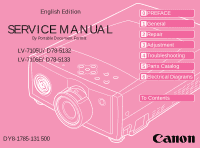
English Edition SERVICE MANUAL By Portable Document Format LV-7105U/D78-5132 LV-7105E/D78-5133 0 PREFACE 1 General 2 Repair 3 Adjustment 4 Troubleshooting 5 Parts Catalog 6 Electrical Diagrams To Contents DY8-1785-131 500 - Canon LV-7105 | Service Manual - Page 2
- Canon LV-7105 | Service Manual - Page 3
CANON Multimedia Projector LV-7105U D78-5132 LV-7105E D78-5133 SERVICE SMANUAL - Canon LV-7105 | Service Manual - Page 4
) alteration, translation into another language, or other use of the data in whole or part, contained on this CD-ROM without the written consent of Canon Inc., is prohibited. PDF Files This CD-ROM contains PDF files created using Adobe® Acrobat® 4.0J. PDF files can be viewed using Adobe® Acrobat - Canon LV-7105 | Service Manual - Page 5
between the models are cosmetic, mainly the designation and rating plates. Internally, they are identical. Main Marketing Area Japan North America Europe Model Name POWER PROJECTOR MULTIMEDIA PROJECTOR MULTIMEDIA PROJECTOR LV-7105J LV-7105U LV-7105E I - Canon LV-7105 | Service Manual - Page 6
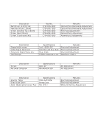
1) General Purpose Tools Description Ball Driver, 2.0mm hex Hex Key Set (w/2.0mm) Driver, Ceramic Tip (1.8mm) Driver, Slot (4.0mm) Driver, Cross-point (#2) Tool No. Adjustment All Adjustment 4) Chart/Software (Attached with this manual) Description Monitor Tester Gray Scale Chart Color Shading - Canon LV-7105 | Service Manual - Page 7
1-1 1.2 Major Features 1-2 1.3 LV-7105 Features (Details 1-3 2. LV-7105 SPECIFICATIONS 1-5 2.1 Main unit 1-5 PROJECTOR 1-18 6.1 Positioning the projector 1-18 6.2 Installation precautions 1-18 7. SUPPORTED COMPUTER SYSTEM MODE 1-20 Part 2: Repair Information 1. SAFETY INSTRUCTIONS - Canon LV-7105 | Service Manual - Page 8
2-14 5. LCD PANEL/PRISM ASS'Y REPLACEMENT 2-15 5.1 LCD Panel/Prism Ass'y Removal 2-15 5.2 Note on LCD Panel/Prism Ass'y Mounting 2-16 6. CLEANING...2-17 7. LAMP REPLACEMENT 2-18 Part 3: Adjustment 1. BEFORE ADJUSTMENTS 3-1 1.1 Adjustments after Parts Replacement 3-2 1.2 Service Adjustment Menu - Canon LV-7105 | Service Manual - Page 9
4. TEST POINTS AND LOCATIONS 3-20 Part 4: Troubleshooting 1. TROUBLESHOOTING 4-1 1.1 No Power 4-1 1.2 No Sound 4-6 1.3 No Picture 4-7 2. CONTROL PORT FUNCTIONS 4-9 2.1 System Control & I/O Port Functions 4-9 3. WAVEFORMS 4-11 4. IC BLOCK DIAGRAMS 4-14 Part 5: Parts Catalog Part 6: - Canon LV-7105 | Service Manual - Page 10
- Canon LV-7105 | Service Manual - Page 11
Part 1 General Information - Canon LV-7105 | Service Manual - Page 12
- Canon LV-7105 | Service Manual - Page 13
. The LV-7105 will be added to the LV-5100 lineup of projectors equipped with SVGA panels as Canon continues to expand its multimedia projector product offerings. Canon is responsible for the external design and projection lens. *Microportable: Defined by Canon to mean an LCD projector that weighs - Canon LV-7105 | Service Manual - Page 14
, class-leading 800 ANSI lumen output q Supports HDTV&DVD component input Beautiful image reproduction with minimal burring of color q Equiped with Digital Keystone function Smoothly corrects for "keystone" effect caused by projector - Canon LV-7105 | Service Manual - Page 15
Information 1.3 LV-7105 Features (Details) q Brightest in the SVGA Micro Projector class - 800 ANSI Lumens 1) Large screen presentation even in brightly lit conference rooms 2) 120W UHP short arc lamp for bright images with great color balance 3) Newly developed large apature projection lens (f=28 - Canon LV-7105 | Service Manual - Page 16
or used as a rear-screen projector. q Reduced lamp problems (Replace Lamp Indication) 1) The replace lamp indicator shows when it is time for a change. 2) Lamp replacement by the user is simple. q The design emphasizes the lens, as you would expect from a Canon product. * With digital compression - Canon LV-7105 | Service Manual - Page 17
Part 1: General Information 2. LV-7105 SPECIFICATIONS 2.1 Main unit 1. Type: Micro-portable LCD Projector 2. LCD panel: 0.7" polysilicon active matrix TFT x 3 4:3 aspect ratio 3. Number of pixels: 786,432 pixels (1024 H x 768 V) x 3 4. Resolution of display supported: SXGA (compression)/XGA/ - Canon LV-7105 | Service Manual - Page 18
1. Remote Control Transmitter with two AA alkaline batteries 2. VGA Cable 3. Control Cable for PS/2 port 4. Lens Cover 5. Carry Bag 6. AC Power Cord 7. Plug Adapter (Japan model only) 8. Warranty Card 9. Owner's Manual 2.4 Other specifications Service life of lamp: Approx. 1000 hours 1-6 - Canon LV-7105 | Service Manual - Page 19
3.1 Main unit Zoom ring Projection Lens Focus Ring Part 1: General Information Speaker Air Intake Vent Lens Cover Power Cord Connector Infrared Remote Receiver Foot Lock Latch Terminals and Connectors Air Intake Vent Exhaust Vent Air Intake Vent Lamp Cover Air Filter Adjustable Foot - Canon LV-7105 | Service Manual - Page 20
picture size. READY INDICATOR This indicator lights green when the projector is ready to be turn on. And it flashes green in Power Management mode. WIDE TELE POWER MENU NORMAL MODE LAMP REPLACE WARNING TEMP. READY LAMP MODE BUTTON Use to select input source either Computer or Video - Canon LV-7105 | Service Manual - Page 21
processor may malfunction and need to rest. This can be done by pressing the Reset button with a pen, which will shut down and restart the projector. VIDEO S - VIDEO Y - Pb/Cb - Pr/Cr RESET AUDIO OUT AV COMPUTER IN COMPUTER AUDIO IN CONTROL PORT AUDUO OUTPUT Mini stereo Jack Connect the - Canon LV-7105 | Service Manual - Page 22
(Red) 14 Vert. sync. 7 Ground (Green) 15 Reserved 8 Ground (Blue) 3.5 Control port connector When controlling the computer with the remote control of this projector, connect the mouse port of the personal computer to this terminal. This terminal does not adapt the PC98 type mouse port. 876 5 43 - Canon LV-7105 | Service Manual - Page 23
Part 1: General Information ALL OFF ON 3.6 Remote control D.ZOOM BUTTON KEYSTONE BUTTON Used to correct the keystone distortion. POWER KEYSTONE D.ZOOM VOLUME MUTE BUTTON MENU BUTTON POINT BUTTON Used to move a pointer on the menu, to adjust the item, or to pan the image in Digital Zoom mode. - Canon LV-7105 | Service Manual - Page 24
for the remote control is approximately 5m (16.4') and 60˚ in front of the projector. Precautions • Prevent the direct sunlight or strong light from lighting apparatus from striking the infrared remote receiver on the projector. • Do not look into the laser pointer exit or point it at others. • Do - Canon LV-7105 | Service Manual - Page 25
as the other Canon Multimedia Projectors, are outlined below. q External Styling The body is designed with subtle curves and the coloring and semi-transparent body panels follow the lead of the LV-7300 series. Indications of the excellent lens performance are printed around the lens to convey an - Canon LV-7105 | Service Manual - Page 26
measuring the temperature in the area of the LCD panels. The outputs of the sensors are sent or the temperature sensed by sensor 2 exceeds 57˚C, the lamp is extinguished. In this case, the main power switch immediately shuts down the projector. 5. In Service Mode (when operating at high altitude) - Canon LV-7105 | Service Manual - Page 27
Part 1: General Information Fan Drive Voltage Fan Noise: 39dB 13V 12V 11V Exhaust Fan 10V 9V Intake Fan Fan Noise: 43dB Room Temperature: Sensor 1: Sensor 2: 27ûC 35ûC 37ûC 41ûC 49ûC 51ûC 47ûC 55ûC 57ûC Fig. 1-9 Unit shutdown Temperature 1-15 - Canon LV-7105 | Service Manual - Page 28
Input Audio Amplifier Speaker (Stereo) MAC Adapter Set the switches as shown in the table below depending on the Display Resolution that you want to use before you turn-on the projector and computer. ON OFF ON DIP 123456 1 2 3 4 56 13" MODE (640 x 480) ON ON OFF OFF OFF OFF 16" MODE - Canon LV-7105 | Service Manual - Page 29
Cassette Recorder Video Disc Player Component video output equipment (DVD Player, HDTV, etc.) Composite Video Output Component Video Output Y Pb/Cb Pr/Cr S-VIDEO Output Audio Output RL When several display signals are input, the projector assigns priority in this order: (1) Y, Pb/Cb, Pr/Cr - Canon LV-7105 | Service Manual - Page 30
the way of this hot air. 2) Installation site Do not install the projector in humid or duty locations, or locations subject to a lot of optical parts, resulting in impaired image quality. Also, do not install the projector in high- or low-temperature locations. 3) Operating temperature range: 5˚C - Canon LV-7105 | Service Manual - Page 31
Part 1: General Information in blurred images. 6) Screen and room brightness Do not install the projector where sunlight or lighting directly strikes on the screen. If sunlight or light from lighting strikes on the screen, image will appear whitish and difficult-to-view. 1-19 - Canon LV-7105 | Service Manual - Page 32
General Information 7. SUPPORTED COMPUTER SYSTEM MODE The projector judges the incoming . (Adjust and set the computer system manually.) Table 1-1 ON-SCREEN DISPLAY RESOLUTION VGA 1 640 x 480 H-Freq. (kHz) 31.47 V-Freq. (Hz) 59.88 ON-SCREEN DISPLAY RESOLUTION XGA 10 1024 x 768 H-Freq. - Canon LV-7105 | Service Manual - Page 33
Part 2 Repair Information - Canon LV-7105 | Service Manual - Page 34
- Canon LV-7105 | Service Manual - Page 35
PROTECTIVE SHIELD IN POSITION AND PROPERLY SECURED. 4: Before replacing the cabinet cover, thoroughly inspect the inside of the cabinet to see that no stray parts or tools have been left inside. Before returning any projector to the customer, the service personnel must be sure it is completely safe - Canon LV-7105 | Service Manual - Page 36
. 2.1 Fuse The fuse is located inside of the projector. When either the LAMP indicator or the READY indicator is not illuminated, fuse may FUSE INC. TYPE 215004 Screw Line Filter Cover Line Filter Board [How to replace the fuse] 1. Remove the cabinet top and main board following to "Mechanical - Canon LV-7105 | Service Manual - Page 37
instructions in the "Air filter care and cleaning" below. • Ventilation slots of the projector are blocked. In such an event, reposition the projector so that ventilation slots are not obstructed. • Check if projector lens of the projector. Air filters outlet. 2. Turn the projector up side down and - Canon LV-7105 | Service Manual - Page 38
it. We recommend to avoid dusty, smoky place for operating the projector. Using in dusty place may cause the picture of poor quality. When using under the dusty or smoky conditions, dust may accumulate on the LCD panel and lens inside it, and may resultantly be projected on the screen together with - Canon LV-7105 | Service Manual - Page 39
Part 2: Repair Information 3. MECHANICAL DISASSEMBLIES Mechanical disassemble should be made following procedures in numerical order. Following steps show the basic procedures, therefore unnecessary step may be ignored. CAUTION The parts and screws should be placed exactly the same position as - Canon LV-7105 | Service Manual - Page 40
Part 2: Repair Information 3.3 Main Board Removal 1. Remove 9 screws and remove the main board upward. Main Board Fig. 2-6 3.4 Fuse Removal 1. Remove a screw and pull the line filter cover upward and then replace the fuse if required. Line Filter Cover Fuse Fig. 2-7 2-6 - Canon LV-7105 | Service Manual - Page 41
Part 2: Repair Information 3.5 AV and Component Board Removal 1. Remove 3 screws A and FPC cables, and then take the component board off upward. 2. Remove a screw B and a grounding lead, and then take the AV board ass'y off upward. A Component Board A A AV Board Ass'y B Grounding Lead Fig. 2-8 - Canon LV-7105 | Service Manual - Page 42
ballast board off from the holder. 5. Remove the fan FN905 from the holder. C Thermal Switch Sockets A Lamp Ballast Unit Blue Brown D Lamp Ballast Board D D D B Lamp Socket B Fig. 2-10 3.8 Power Board Removal 1. Remove 2 screws A and take the power unit cover off upward. A 2. Remove - Canon LV-7105 | Service Manual - Page 43
socket. 3. Remove 7 screws C and pull the optical unit upward. C C A Thermal Switch A 4. Remove 2 screws D and fan (FN901). B Lamp Socket C C C C C AV Board Ass'y Optical Unit Fan (FN901) 3.10 Audio Amp. Board Removal 1. Remove a screw A (bottom side) and 2 screws B, and then pull the power - Canon LV-7105 | Service Manual - Page 44
Part 2: Repair Information 3.11 Fans (FN902, FN903, FN904) Removal 1. Remove 4 screws A and 3 screws B and remove the duct cover and fans (FN902 and FN903). A 2. Remove 2 screws C and A fan (FN904), and remove 2 screws D and fan holder. FN902 A B BB A Duct Cover FN903 C C FN904 Fig. - Canon LV-7105 | Service Manual - Page 45
1. Remove the Cabinet top and cabinet front following to "Mechanical Disassemblies". 2. Remove 4 screws and remove the Projection Lens. Fig. 2-16 4.2 Optical Unit Top Removal 1. Remove the Cabinet top, front, main board, component boards and power unit cover following to "Mechanical Disassemblies - Canon LV-7105 | Service Manual - Page 46
off upward. 3. Release 4 hooks B on the holder and remove the integrator lens. A A * Should be place the rugged surface of lens comes to holder side. Hooks B Holder Integrator Lens Hooks B Fig. 2-18 4.4 Relay Lens Ass'y Disassembly 1. Remove the cabinet top, front, main and component boards - Canon LV-7105 | Service Manual - Page 47
and take the each polarized glass-out off upward. Note: Do not replace the LCD panel separately otherwise it can not obtain proper picture. LCD Panel/Prism Ass'y LCD Panel/Prism Ass'y Polarized Glass-Out LCD Panel * Mount the polarized glass as the surface attached the phase sheet comes to the - Canon LV-7105 | Service Manual - Page 48
When the optical parts mounting or assembling, the parts must be mounted in the specified location and direction. Please follow to the figure below. No. Part name 1 Prism ass'y 2 Integrator lens (IN) 3 Integrator lens (OUT) 4 Prism Ass'y (PBS) 5 Condenser lens (OUT) 6 Dichroic mirror (R) 7 Mirror - Canon LV-7105 | Service Manual - Page 49
this manual. COLOR SHADING CORRECTION (Ver. 2.0.2) 5.1 LCD Panel/Prism Ass'y Removal 1. Remove the cabinet top, front and main board following to "Mechanical Disassemblies". 2. Remove 4 screws by using the 2.0 mm hex driver and take the LCD Panel/Prism ass'y off upward from Note: Do not replace - Canon LV-7105 | Service Manual - Page 50
. If the focus adjustment is required, please adjust the positioning of LCD Panel/Prism Ass'y by following the below procedure. Mounting Procedure 1. Loosen 4 screws A on the LCD Panel/Prism ass'y with 2.0 mm hex driver. 2. Turn the projector on and project the image with WIDE zoom, and adjust the - Canon LV-7105 | Service Manual - Page 51
of use, dust and other particles will accumulate on the LCD panel, prism, mirror, polarized glass, lens, etc., causing the picture to darken or color to Optical Unit Disassemblies". If the LCD panel needs cleaning, remove the LCD panel unit following to "LCD panel replacement". 3. Clean the optical - Canon LV-7105 | Service Manual - Page 52
7. Reset the lamp replacement monitor timer, see below explanation. Lamp cover Handle Service Parts No.: DY4-6108-000 Description: Lamp A'ssy LV-LP10 Lamp Assembly Fig. 2-25 CAUTION • Do not reset the Lamp Replacement Monitor Timer, except after the lamp is replaced. • The projector can not be - Canon LV-7105 | Service Manual - Page 53
illuminate when the accumulated illumination time of the lamp reaches 1000 hours. This is to indicate that lamp replacement is required. You can check the accumulated illumination time of the lamp by following procedure. 1. Press and hold the pointer on the projector for more than 20 seconds. 2. The - Canon LV-7105 | Service Manual - Page 54
- Canon LV-7105 | Service Manual - Page 55
Part 3 Adjustment - Canon LV-7105 | Service Manual - Page 56
- Canon LV-7105 | Service Manual - Page 57
the memory IC (IC302) is replaced. (Lamp replacement monitor time can not be set to the previous value.) CAUTION Caution to memory IC replacement When IC302 is replaced with new one, the CPU writes down the default data of the service adjustments to the replaced IC, refer to the service adjustment - Canon LV-7105 | Service Manual - Page 58
PC/AV signal adjustment-1 PC/AV signal adjustment-2 S/H clock adjustment Common center adjustment White balance adjustment Black balance adjustment LCD/ Prism Ass'y r r Integrator lens q Disassembly / Replaced Parts Relay Lens Polarized glass RG B Power Board Component Board Main Board - Canon LV-7105 | Service Manual - Page 59
to the normal mode To exit the service mode, press the POWER button on the projector or remote control unit. Normal mode Service mode Service Mode Video Item Data 10 15 Version : 1.0 WIDE TELE POWER MENU NORMAL MODE LAMP REPLACE WARNING TEMP. READY LAMP Item 10 Data 15 Adjustment - Canon LV-7105 | Service Manual - Page 60
conditions listed below. If you can not keep the one of following conditions, the projector turns off automatically by operating the protection circuit. Service Conditions: Operating Temperature : 41°F ~ 81°F (5°C ~ 30°C) Fans Control : Maximum AC Power Supply : 100 ~ 120V or 200V ~ 240V To set - Canon LV-7105 | Service Manual - Page 61
baud rate setting 24 Lamp life time display 25 IC Control and User control spec) 70 70 70 0 - 125 B-Bias adjust value(refer to DAC IC Control and User control spec) 20 20 0 - 63 Sub-CONT(refer to DAC IC Control and User control spec) 17 0 - 255 Display Blue test pattern where Service - Canon LV-7105 | Service Manual - Page 62
4 0 - 15 Refer to User control spec Refer to User control spec Select the PW Filter Refer to Use control spec. -- Video and S-Video mode only. -- -- ↓ -- For Component mode -- ↓ -- ↓ -- ↓ -- For Component mode and RGB HDTV 1035i -- ↓ -- ↓ -- ↓ -- For Component mode and RGB - Canon LV-7105 | Service Manual - Page 63
control mode "NORMAL" mode unless otherwise noted. Note: * Please refer to "Service Adjustment Menu Operation" for entering to the service mode and adjusting the service data. 2.1 Output Voltage Adjustment After replacing the Power Board, PF.C. Board, readjust the Output voltage adjustment as - Canon LV-7105 | Service Manual - Page 64
gray scale computer signal. 2. Set to COMPUTER mode. [R-Offset adjustment] 3. Connect an oscilloscope to test point "TP2211R" (+) and chassis ground (-). 4. Enter to the service mode, select item no. "275" and change data value to adjust the pedestal level and black level to be same level. [G-Offset - Canon LV-7105 | Service Manual - Page 65
. 2. Set to VIDEO (Component) mode. [Component-R gain adjustment] 3. Connect an oscilloscope to test point "TP2211R" (+) and chassis ground (-). 4. Enter to the service mode, select item no. "30" and change data value to adjust "a" to be 1.05 ±0.01Vp-p. [Component-G gain adjustment] 5. Connect an - Canon LV-7105 | Service Manual - Page 66
the 16-step gray scale video signal. 2. Set to VIDEO mode. 3. Connect an oscilloscope to test point "TP2221G" (+) and chassis ground (-). 4. Enter to the service mode, select item no. "30" and change data value to adjust "a" to be 1.05 ±0.01Vp-p. (a) Pedestal level = Black level Fig. 3-5 2.7 PSIG - Canon LV-7105 | Service Manual - Page 67
16-step gray scale computer signal. 2. Set to COMPUTER mode. 3. Connect an oscilloscope to test point "TP503G" (+) and chassis ground (-). 4. Enter to the service mode, select item no. "0" and change data value to adjust "a" to be 1.40 ±0.01Vp-p. [AV-gamma off adjustment] 5. Receive the 16-step gray - Canon LV-7105 | Service Manual - Page 68
to adjust "a" to be 4.00 ±0.01Vp-p. [B-video adjustment] 10. Connect an oscilloscope to test point "TP505B" (+) and chassis ground (-). 11. Enter to the service mode and select COMPUTER mode. 12. Select item no. "14" and change data value to adjust "a" to be 4.00 ±0.01Vp-p. 13. Select VIDEO mode and - Canon LV-7105 | Service Manual - Page 69
16-step gray scale computer signal. 2. Set to COMPUTER mode. 3. Connect an oscilloscope to test point "TP503G" (+) and chassis ground (-). 4. Enter to the service mode, select item no. "15" and change data value to adjust "b" to be 1.70 ±0.01Vp-p. [AV-video adjustment-2] 5. Receive the 16-step gray - Canon LV-7105 | Service Manual - Page 70
. 2.14 White Balance Adjustment [PC white balance adjustment] 1. Receive the 16-step gray scale computer signal. 2. Set to COMPUTER mode. 3. Enter to the service mode, select item no. "16" (Red) or "17" (Blue), and change data values respectively to make a proper white balance. [AV white balance - Canon LV-7105 | Service Manual - Page 71
adjustment] 1. Receive the 16-step gray scale computer signal. 2. Set to COMPUTER mode. 3. Enter to the service mode, select item no. "9" (Red) or "10" (Blue), and change data values respectively to make a Correction" software. COLOR SHADING CORRECTION (Ver. 2.0.2) Attached with this manual 3-15 - Canon LV-7105 | Service Manual - Page 72
% of black raster signal. CAUTION Do not disconnect the connectors on main and component boards otherwise the projector can not be turned on. Slot B Polarized glass mounting base Fig. 3-11 [R/G/B-contrast adujstment] 1. Project desired light component on the screen as follows. When adjusting the - Canon LV-7105 | Service Manual - Page 73
a 2.0mm hex driver and a slot screwdriver. • Remove cabinet top following to "Mechanical Disassemblies". CAUTION Do not disconnect the connectors on main and component boards otherwise the projector can not be turned on. [Adjustment]] 1. Turn on lamp by a state of without FPC cable of LCD panels - Canon LV-7105 | Service Manual - Page 74
Part 3: Adjustment a Yellow b a b A Moving of slot B Slot B Fig. 3-13 x Yellow y C C x y Slot D Slot D Moving of Slots D Fig. 3-14 3-18 - Canon LV-7105 | Service Manual - Page 75
Do not disconnect the connectors on main and component boards otherwise the projector can not be turned on. [Adjustment] 1. Turn on lamp by a state of without FPC cable of LCD panels. 2. Adjust the adjustment base of relay lens ass'y to make color uniformity in white. If the color shade appears - Canon LV-7105 | Service Manual - Page 76
Part 3: Adjustment 4. TEST POINTS AND LOCATIONS q Main Board TP506B TP505B VR531 VR562 VR563 TP1571 IC3301 TP1401 VR533 VR532 TP561 TP1531 TP571 IC561 IC531 VR561 TP541 TP504G TP531 TP503G VR501 TP1451 TP501 IC501 TP511 VR503 TP3322 TP3321 TP1501 VR502 TP502R TP501R IC811 - Canon LV-7105 | Service Manual - Page 77
Part 4 Troubleshooting - Canon LV-7105 | Service Manual - Page 78
- Canon LV-7105 | Service Manual - Page 79
Part 4: Troubleshooting 1. TROUBLESHOOTING 1.1 No Power 1) Periphery of chassis 1. Is fuse (F601) blown? Fuse may be opened when either the LAMP indicator or the READY indicator isn't Illuminated. Check the fuse. • For continued safety, replace with a fuse of the same type. TYPE T4.0AH 250V FUSE. ( - Canon LV-7105 | Service Manual - Page 80
4: Troubleshooting 3) signal is correct. Pin 11 of K3D H : ON 8. Check that the LAMP BST_SW signal is correct. Pin 12 of K3D H : ON 9. Check that the Sensor IC(IC2831) detects abnormal temperature inside the projector. 4) Component board 1. Check Power Supply and switching circuit Check ICs IC2641 - Canon LV-7105 | Service Manual - Page 81
Part 4: Troubleshooting 4-3 - Canon LV-7105 | Service Manual - Page 82
Troubleshooting (Power-On: H) LAMP POWER 2 IC301 SYSTEM CONTROL (Power-On: H) LAMP BST_SW. 206 (Power-On: H) 5V_SW. 146 IIC BUS PSDA PSDA 17-18 KEY SW 16 POWER LED IC1803 14 READY LED KEY SWITCHES 15 TEMP LED 13 LAMP REP. LED ON/OFF BUTTON INDICATOR LAMP READY TEMP WARNING LAMP REPLACE - Canon LV-7105 | Service Manual - Page 83
Part 4: Troubleshooting IIC BUS TEMP. the projector. Is projection of lamp cover inside broken or not fitting correctry ? Check the interlock switch (SW904) and lamp cover. is detected at the periphery of lamp driver circuit, the voltage of this line comes HIGH. LAMP.DET CB2 (Error: H) K8CC-1 - Canon LV-7105 | Service Manual - Page 84
Part 4: Troubleshooting 1.2 No Sound 1) Main board 1. Check that the PC/AV switching signal is correct. Pins 10 and 11 of IC5001 AV : L, PC : H 2. Check that audio signal - Canon LV-7105 | Service Manual - Page 85
Part 4: Troubleshooting 1.3 No Picture 1) AV board 1. Check that the Vcc-voltages(+5V, -5V) are applied to AV circuits. Pins 47-50 of K10A, Pins 47-54 of - Canon LV-7105 | Service Manual - Page 86
DCLK/DHS/DVS Part 4: Troubleshooting R PC_R G PC_G B H-SYNC V-SYNC IC1001 IC1002 PC_B 18 4 G-SYNC SEP. 21 SYSTEM CONTROL & SCAN CONV. IC301 R G TP2211R TP2221G B TP2231B 22 24 26 18 LCD 16 DRIVER 14 IC401 IC2211 46 IC2221 43 IC2231 40 D/A IC2200 TPDVS TPDHS GLCD PANEL BLCD PANEL - Canon LV-7105 | Service Manual - Page 87
Part 4: Troubleshooting 2. CONTROL PORT FUNCTIONS 2.1 System Control & I/O Port Functions IC Ref. No Pin/Name I/O IC301 PortA0 I/O PortA1 M_SCL IIC CLK M_SDA IIC DATA Mute Mute Mute-OFF: High LAMP_REP_LED Lamp Replace LED Drive ON: High READY_LED Ready LED Drive ON: High TEMP_LED Temp - Canon LV-7105 | Service Manual - Page 88
Part 4: Troubleshooting IC Ref. No IC1806 IC1807 IC1808 Pin/Name I/O 12 O 13 O 14 O 15 O 16 O 17 O 18 O 19 O 12 O 13 1080i/1035i/720p:Low,others to High Abnormal: Low Normal: High Lamp Fail Abnormal: High Normal: Low S-Input Detection Component-Input Detection Component - Canon LV-7105 | Service Manual - Page 89
3. WAVEFORMS TP218 TP208 AV VIDEO TP207 TP7223 AV H-SYNC Part 4: Troubleshooting TP7224 AV V-SYNC TP221R TP221G TP221B VIDEO TPDHS DHS TP1401 TP1451 PSIG for R/B and G TPDVS DVS TP2211R D/A R-OUTPUT 4-11 - Canon LV-7105 | Service Manual - Page 90
Part 4: Troubleshooting TP2221G D/A G-OUTPUT TP501 S&H R-INPUT TP511 TP1501 S&H R-OUTPUT TP501R TP502R S&H R-OUTPUT TP2231B D/A B-OUTPUT TP531 S&H G-INPUT TP541 TP1531 S&H G-OUTPUT TP503G TP504G S&H G-OUTPUT 4-12 - Canon LV-7105 | Service Manual - Page 91
TP561 S&H B-INTPUT TP571 TP1571 S&H B-OUTPUT TP505B TP506B S&H B-OUTPUT Part 4: Troubleshooting 4-13 - Canon LV-7105 | Service Manual - Page 92
Part 4: Troubleshooting 4. IC BLOCK DIAGRAMS q AN5265 q FA5332M 4-14 - Canon LV-7105 | Service Manual - Page 93
Part 4: Troubleshooting q PW164-10RK q CXA2111R 4-15 - Canon LV-7105 | Service Manual - Page 94
Part 4: Troubleshooting q M62358FP q CXD3503R 4-16 - Canon LV-7105 | Service Manual - Page 95
Part 4: Troubleshooting q CXA2112R q STR-Z2156 4-17 - Canon LV-7105 | Service Manual - Page 96
Part 4: Troubleshooting q IDT71V016S q CXA2016S 4-18 - Canon LV-7105 | Service Manual - Page 97
q MC10H351ML Part 4: Troubleshooting q LM76CHMX 4-19 - Canon LV-7105 | Service Manual - Page 98
Part 4: Troubleshooting q AV9155C 11 19 SCLK20-22 20 2 14.318MHz crystal 3 14.318MHz 13 14.318MHz 14 3 REFERENCE CLOCK 16 VDD 15 GND CPU CLOCK - Canon LV-7105 | Service Manual - Page 99
q TC4053BF Part 4: Troubleshooting q SAA7114H 4-21 - Canon LV-7105 | Service Manual - Page 100
Part 4: Troubleshooting 4-22 - Canon LV-7105 | Service Manual - Page 101
Part 5 Parts Catalog - Canon LV-7105 | Service Manual - Page 102
- Canon LV-7105 | Service Manual - Page 103
Multimedia Projector LV-7105U LV-7105E Power Projector LV-7105J REF.NO.D71-5132 D71-5133 D71-5131 PARTS CATALOG - Canon LV-7105 | Service Manual - Page 104
- Canon LV-7105 | Service Manual - Page 105
Page 1 CANON LV-7105J LV-7105U LV-7105E 42 42 12 REF. No. D78-5131 D78-5132 D78-5133 1 d 42 47 25 47 46 42 46 46 46 46 46 46 6 b 36 - Canon LV-7105 | Service Manual - Page 106
000 C 8 DY4-6022-000 C 9 DY4-6023-000 E 10 DY4-6024-000 E 1 CAP, LENS 1 PLATE, AV 1 WINDOW, R/C SENSOR 1 FILTER, DUST, L 1 FILTER, DUST, R 11 AV 1 PANEL, TOP COVER 1 PLATE, LIGHT SHIELD 1 HOLDER, SENSOR 1 HOLDER, LAMP BALLAST 24 DY4-6032-000 C 25 DY4-6033-000 C 26 DY4-6034-000 C - Canon LV-7105 | Service Manual - Page 107
Page 2 CANON LV-7105J LV-7105U LV-7105E 45 77 REF. No. D78-5131 D78-5132 D78-5133 22 69 48 48 76 45 48 80 48 75 44 44 44 44 45 48 45 45 79 78 62 70 50 50 50 50 45 45 21 63 - Canon LV-7105 | Service Manual - Page 108
75 DY4-6064-000 C 76 DY4-6065-000 C 77 DY4-6066-000 C 78 DY4-6067-000 C 79 DY4-6068-000 C 4 SCREW 1 PRISM/LCD ASS'Y 1 LENS, INTEGRATOR IN 1 LENS, RELAY OUT 1 LENS, PROJECTION 1 GLASS, PL IN, R 1 GLASS, PL IN, G 1 GLASS, PL IN, B 1 GLASS, PL OUT, R 1 GLASS, PL OUT, G 80 DY4-6069-000 - Canon LV-7105 | Service Manual - Page 109
Page 3 CANON LV-7105J LV-7105U LV-7105E REF. No. D78-5131 D78-5132 D78-5133 73 74 (69) 73 72 (80) (78) (77) 67 (75) 71 (76) (79) 66 81 68 82 65 61 64 (63) - Canon LV-7105 | Service Manual - Page 110
. DY4-6050-000 DY4-6052-000 DY4-6053-000 DY4-6054-000 DY4-6055-000 CLASS C C C C C QTY 1 1 1 1 1 DESCRIPTION PRISM, PBS LENS, INTEGRATOR IN LENS, INTEGRATOR OUT LENS, CONDENSER OUT LENS, CONDENSER, G 67 DY4-6056-000 C 68 DY4-6057-000 C (69) DY4-6058-000 C 71 DY4-6060-000 C 72 DY4-6061 - Canon LV-7105 | Service Manual - Page 111
Page 4 CANON LV-7105J LV-7105U LV-7105E A100 REF. No. D78-5131 D78-5132 D78-5133 A200 POWER P.C.B. A001 L903 SW902 A901 SW904 FN905 A1000 IL901 FN901 L901 L902 FN902 A2800 A1800 F601 A600 FN903 SP901 FN904 LP900 - Canon LV-7105 | Service Manual - Page 112
1 1 1 DESCRIPTION PCB ASS'Y, AUDIO PCB ASS'Y, MAIN PCB ASS'Y, COMPONENT PCB ASS'Y, LINE FILTER LAMP BALLAST ASS'Y 1 PCB ASS'Y, AV 1 PCB ASS'Y, TEMP 1 PCB ASS'Y, R/C 1 PCB ASS CORE 1 FERRITE CORE 1 FERRITE CORE 1 LAMP ASS'Y, LV-LP10 1 SPEAKER 1 SWITCH, THERMAL 1 SWITCH, PUSH Page 4 REMARKS 250V 4A - Canon LV-7105 | Service Manual - Page 113
Page 5 CANON LV-7105J LV-7105U LV-7105E U-1 U-2 W-1 REF. No. D78-5131 D78-5132 D78-5133 V-1 V-2 X-1 Z - Canon LV-7105 | Service Manual - Page 114
-000 CY2-8299-000 CLASS C B D D D QTY 1 1 1 1 1 DESCRIPTION REMOTE CONTROLLER, LV-5100 COVER, REMO-CON BATTERY POWER CORD, AC120V POWER CORD, AC240V POWER CORD, AC100V V-2 CY2-8288-000 1 CABLE, MOUSE CONTROL PS/2 1 BAG, CARRYING Page 5 REMARKS FOR LV-7105U FOR LV-7105E FOR LV-7105J FOR LV-7105J - Canon LV-7105 | Service Manual - Page 115
Page 6 PARTS LIST REF.NO. D78-5131 D78-5132 D78-5133 PAGE 1 2 4 4 5 NEW SYMBOL 53 50 SP901 SW904 V-2 PARTS NO. CY2-8231-000 CY2-8232-000 CY2-8274-000 CY2-8277-000 CY2-8288-000 QTY 2 4 1 1 1 PAGE 1 1 1 1 1 NEW SYMBOL 28 29 30 31 33 PARTS NO. DY4-6036-000 DY4-6037-000 DY4-6038-000 DY4-6039- - Canon LV-7105 | Service Manual - Page 116
PARTS LIST REF.NO. D78-5121 D78-5122 D78-5123 PAGE 1 1 1 1 1 NEW * * * * * SYMBOL c 2 4 6 32 1 2 * 2 * 5 * 4 * 37 62 70 Z A901 4 * 4 * 4 * 4 * 4 * FN904 LP900 A100 A1800 A1000 4 * A200 4 * A2800 4 * A001 4 * A600 4 * POWER PARTS NO. DY4-6097-000 DY4-6098-000 - Canon LV-7105 | Service Manual - Page 117
- Canon LV-7105 | Service Manual - Page 118
Part 6 Electrical Diagrams - Canon LV-7105 | Service Manual - Page 119
- Canon LV-7105 | Service Manual - Page 120
Part 6: Electrical Diagrams 1. PARTS DESCRIPTION AND READING IN SCHEMATIC DIAGRAM 1. The parts specification of resistors, capacitors and coils are expressed in designated code. Please check the parts description by the following code table. 2. Some of transistors and diodes are indicated in mark - Canon LV-7105 | Service Manual - Page 121
Part 6: Electrical Diagrams Resistor Reading Example 1/2 D J 10K B q Material table Example 6 W K 8.2 Characteristic Z (Carbon fuse) B (Non-burnable) Example 1/2 C K 1M K indicates in KΩ M indicate in MΩ Resistance value Tolerance (see below table) Material (see below table) Rated wattage - Canon LV-7105 | Service Manual - Page 122
Part 6: Electrical Diagrams 2. PIN DESCRIPTION OF DIODE, TRANSISTOR AND IC q DqioDdeiode K A q TrqaTnrsainsstiostro/rF/FEETT E C B C E B C E B B E C q ICq IC K A K AA A K KK A K K: Cathode A: Anode A E C B C BCE C BE C1 C2 B1 E B2 C2 B1 E1 Index E2 B2 C1 C1 C2 E E1 - Canon LV-7105 | Service Manual - Page 123
(LV-7105U/LV- . POWER WARNING READY LAMP REPLACE M_SCL M_SDA IC302 5 6 MEMORY IC806 FLASH ROM LAMP ERR 7 D0-D7 8 IC1808 I/O EXPAND S-SW 2 CB-SW CR-SW 3 4 IC1809 D7-D15 DRE0-7 DGE0-7 DBE0-7 D/A CONVERTER R 4 46 I 31 IC2200 43 G B 40 1 DCLK DVS DHS IC2211 IC2221 IC2231 LCD DRIVER - Canon LV-7105 | Service Manual - Page 124
LV-7105U/LV-7105E) AC CORD ASSY PWB, LINE FILTER F601 FUSE VA601 L601 L602 SW904 SW902 INTER LOCK THERMAL SW. SW. DB611 L611 D612 K6A K6C Q611 R612/ C618 R613 TSW611 IC01 P.F.CONTROL K6F VR01 1 3 LAMP CONTROL 15.5V 15.5V1 R-LCD PANEL G-LCD PANEL B-LCD PANEL K8A K3A 35-38 - Canon LV-7105 | Service Manual - Page 125
LV-7105U 400V 132W 3 LAMP BALLAST A901 1AV4U20B35800 LP901 LENS 1AV4Z10B18300 R620 1/2GJ SUPPLY ASSY,PWB,POWER MP6A SERVICE 1AASB10C3110A R646 1/10 GJ 6.8K replacement of these parts must be made by exactly the same parts. This projector J11EA321G 32 R LCD PANEL G LCD PANEL B LCD PANEL K3M - Canon LV-7105 | Service Manual - Page 126
CRIN (IC5251 3P) B/Cb/Pb CBIN (IC5253 3P) G-Y YIN (IC5252 3P) HSYNC MUTE (IC1803) R3842 1/16 GZ0C (IC1809 5P) CTS/V S5V C3846 25KZ0.1 GQFY RS232C DRIVER IC3871 HIN232CB SP232ACT 9 R2 OUT R2 IN 8 TXD2-DRV 4.3V 10 T2 IN 11 R3891 1/16 GJ100C 12 0V R1 OUT R3884 1/16GJ 100C R3883 - Canon LV-7105 | Service Manual - Page 127
A B C D E F G H I J K L ADCDE1 1/16GZ0C 1/16GZ0C 1/16GZ0C 1/16GZ0C 1/16GZ0C 1/16GZ0C 1/16GZ0C 1/16GZ0C 1/16GZ0C 1/16GZ0C R6979 1/16GZ0C VVS VHS VCLK R1901 1/16GZ 0C R1911 1/16GZ 0C R1921 1/16GZ 0C R1931 1/16GZ 0C S3.3V1 C1902 6.3EM 22D R1905 1/16GZ 0C IC1901 TC7WH125FU C1901 25KZ0.1 GQFY - Canon LV-7105 | Service Manual - Page 128
00102 R1823 1/16GJ 4.7KC R1826 1/16GJ 4.7KC TPPSCL J30A 00102 TEMP.SENS IC K8G J10EG050G 12345 K8G1 K8G2 K8G3 K8G4 K8G5 D1831 1SS355 R1868 1/16GJ 4.7KC R2875 1/16 GZ0C C2851 25KZ0.1 GQFY D2861 SML-210YTLG LAMP REPLACE (YELLOW) D2863 SML-210LTMG WARNING TEMP. (RED) D2864 SML-210PTKG READY - Canon LV-7105 | Service Manual - Page 129
41 42 GAMR_WHG 43 GAMG_WHG 44 GAMB_WHG 45 GAMR_B1G 46 GAMG_B1G 47 GAMB_B1G 48 GAMR_B2G 49 GAMG_B2G 50 GAMB_B2G 51 SCL 52 SDA IC401 CXA2111R LCD DRIVE BIN 26 CLPLEV 25 GIN 24 ATT 23 RIN 22 VCC 21 CLPPLS 20 GND 19 ROUT 18 PVCC 17 GOUT 16 PGND 15 - Canon LV-7105 | Service Manual - Page 130
A A B C D E F G H I J K POWER_FAIL FCNT1 FCNT2 (Q1822) PSCL PSDA (Q1821) (IC1804 19P) FANDRIVE_SW (IC1808 6P) POWER_FAIL COMPONENT K8A6 BOARD "K3A" K8A J10DT600G 24 6 8 10 12 14 16 18 20 22 24 26 28 30 32 34 36 38 40 42 44 46 48 50 52 54 56 58 60 1 3 5 7 9 11 13 15 17 19 21 23 25 - Canon LV-7105 | Service Manual - Page 131
14 VSIG12 13 VSIG11 12 VSIG10 11 VSIG9 10 VSIG8 9 VSIG7 8 VSIG6 7 VSIG5 6 VSIG4 5 VSIG3 4 VSIG2 3 VSIG1 K5G2 2 VSSGR K5G1 1 PSIG G G-LCD PANEL C2542 25KZ0.1GQFY C2544 25KZ0.1GQFY C2546 16EM100D ;16EM100F1 C2540 25EM 22WR B-PANEL C2541 25KZ0.1 GQFY C2543 25KZ0.1 GQFY K5B J11EA321G - Canon LV-7105 | Service Manual - Page 132
LV-7105U/E) Power Board (SIDE:A) CAUTION This projector is isolated from AC line by using the internal converter transformer. Please pay attention to the following notes in servicing Board (SIDE:A) Main Board "K1" A10 HIC Board "K1A" Lamp Ballast Unit Audio Amp Board (SIDE:A) Main Board "K5S" - Canon LV-7105 | Service Manual - Page 133
Board AV Board (SIDE:A) R/C Board (SIDE:A) Main Board "K8D" "K50B" "K50A" Component Board (SIDE:A) Main Board "K33B" FN902 FN904 B-LCD R-LCD G-LCD Panel "K33G" Main Board "K8A" Main Board "K33R" AV Board (SIDE:B) R/C Board (SIDE:B) Component Board (SIDE:B) (PCB_MP6PA/PP6PA) A11 - Canon LV-7105 | Service Manual - Page 134
Main Board (SIDE:A) A12 Main Board (SIDE:B) Speaker Audio Amp Board "K6T" FN905 Component Board "K3R" FN903 Lamp Ballast Unit Audio Amp Board "K6P" Component Board "K3A" FN901 Component Board "K3B" R/C Board "K28D" Temp Board "K8H" Component Board "K3G" Power Board "K6J" Power
-
 1
1 -
 2
2 -
 3
3 -
 4
4 -
 5
5 -
 6
6 -
 7
7 -
8
-
9
-
10
-
11
-
12
-
13
-
14
-
15
-
16
-
17
-
18
-
19
-
20
-
21
-
22
-
23
-
24
-
25
-
26
-
27
-
28
-
29
-
30
-
31
-
32
-
33
-
34
-
35
-
36
-
37
-
38
-
39
-
40
-
41
-
42
-
43
-
44
-
45
-
46
-
47
-
48
-
49
-
50
-
51
-
52
-
53
-
54
-
55
-
56
-
57
-
58
-
59
-
60
-
61
-
62
-
63
-
64
-
65
-
66
-
67
-
68
-
69
-
70
-
71
-
72
-
73
-
74
-
75
-
76
-
77
-
78
-
79
-
80
-
81
-
82
-
83
-
84
-
85
-
86
-
87
-
88
-
89
-
90
-
91
-
92
-
93
-
94
-
95
-
96
-
97
-
98
-
99
-
100
-
101
-
102
-
103
-
104
-
105
-
106
-
107
-
108
-
109
-
110
-
111
-
112
-
113
-
114
-
115
-
116
-
117
-
118
-
119
-
120
-
121
-
122
-
123
-
124
-
125
-
126
-
127
-
128
-
129
-
130
-
131
-
132
-
133
-
134
 |
 |
SERVICE MANUAL
English Edition
LV-7105U/D78-5132
LV-7105E/D78-5133
By Portable Document Format
1
General
0
PREFACE
2
Repair
3
Adjustment
4
Troubleshooting
5
Parts Catalog
6
Electrical Diagrams
To Contents
DY8-1785-131 500