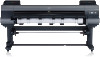
Canon imagePROGRAF iPF9400 Setup Guide - Page 3
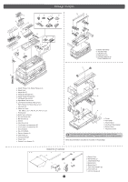
Left Stand Leg, Right, Stand Leg, Bottom Stand, Bottom Stand Stay, Right Stand Leg, Allen Wrench,
 |
View all Canon imagePROGRAF iPF9400 manuals
Add to My Manuals
Save this manual to your list of manuals |
Page 3 highlights
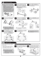
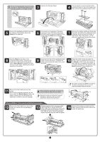
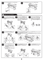
Assemble the Stand • Stand assembly requires two or more people working on a flat floor. Assembling the Stand Caution alone may cause injury or accidental bending of the Stand. • Stand casters are locked at the time of factory shipment. Do not release the lock until the Stand has been fully assembled. In addition, release the lock before moving the Stand. Moving the Stand while the casters are locked may scratch the floor or cause injury. • Do not remove the pieces attached to the casters to prevent slippage before the printer is mounted on the Stand. Removing the pieces may cause the Stand to slip, which may damage the printer or bend the Stand. If the stand slips, the floor may be scratched or injury may be caused. 1 Position the Left Stand Leg and Right Stand Leg so that the markings on the bottom are right-side up and can be read. Insert the left side of the Bottom Stand Stay into the side slot (a) of the Left Stand Leg, and insert the right side of the Bottom Stand Stay into the side slot (b) of the Right Stand Leg. 2 Secure the Bottom Stand Stay to the Left Stand Leg and Right Stand Leg using four M4 hex screws on each side by the Allen Wrench. 3 Hold one end of the Stand while a partner holds the other end. At the same time, rotate both ends to stand the Stand upright. a b 4 Insert the left end of the Top Stand Stay into the side hole (a) on the Left Stand Leg, and insert the right end of the Top Stand Stay into the side hole (b) on the Right Stand Leg, pushing the stay in completely. a 5 Secure the Top Stand Stay to the Left Stand Leg and Right Stand Leg using the four M8 hex bolts on each side by the Wrench. • Rotate both ends of the Stand simultaneously when standing the Stand upright. Rotating only one side before the other may bend the Stand and cause problems in assembly. 6 Attach the Leg Cover to the Left Stand Leg and Right Stand Leg. Insert the protrusion (a) of the Leg Cover into the groove (b) of the Top Stand Stay. Insert the protrusion (c) of the Leg Cover into the groove (d) of the Bottom Stand Stay. b • Insert the left end of the Top Stand Stay MEMO first. The right end can only be pushed in to a restricted position. 7 Secure the Leg Cover to the Left Stand Leg and Right Stand Leg using one M4 hex screw on each side. a a • On Tipping installation, do not remove the pieces attached to the Stand casters to Caution prevent slippage yet. ab ba d c d c Install the printer There are two ways to install the printer. Follow either procedure, depending on the number of people for installing the printer. • Tipping Installation: Requires four people Follow the procedure starting at step 1 on page 3. • Lifting Installation: Requires six people Follow the procedure starting at step 12 on page 4. Tipping installation: In the case of installation by four people 1 Remove the packaging material for use in printer installation from the Stand box and put the material against the pallet on both 2 ends, behind the printer. Insert the hands in the holes on both ends of the front surface of the bottom cardboard sheet. While supporting the printer, tip the printer backward 90 degrees to rest the printer on the packaging material used in printer installation. • Tipping installation uses several special parts, including the pieces attached to Stand casters to prevent slippage, the black belts around the printer, and packaging material. Do not remove or cut these parts. Otherwise, Tipping installation is no longer possible. 3
-
 1
1 -
 2
2 -
 3
3 -
 4
4 -
 5
5 -
 6
6 -
 7
7 -
 8
8 -
 9
9 -
10
-
11
-
12
-
13
-
14
-
15
-
16
-
17
-
18
-
19
-
20
 |
 |
