Carvin FET1000 Instruction Manual - Page 30
Connections, Amplifier
 |
View all Carvin FET1000 manuals
Add to My Manuals
Save this manual to your list of manuals |
Page 30 highlights
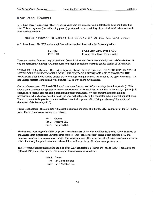
FLT Series Power Amplifiers Connections to the Amplifier Section 4 Section 4 Connections to the Amplifier 'Input Connections A.C. Line Connector: The AC line voltage must match the line voltage selected at the rear of the unit (120 or 220 VAC at 50 or 60 Hz). A detachable 3 pin grounded AC line cord is standard equipment on all units shipped within the United States. The color code of the cord is as follows: Hot (Switched Leg) Neutral EARTH (Chassis Ground) Black White Green w/Yellow Tracer Balanced XLR Inputs: XLR inputs for each channel are provided on the rear panel of the amplifier. These are balanced differential inputs which will provide a very high degree a common mode noise rejection. If you use input cables that are longer than 30 feet it is recommended that you utilize balanced sends with the balanced inputs on your amp to obtain the best noise performance from your system. 1/4" Phone Jack Inputs: These inputs are "stereo phone plug" or "tip, ring, sleeve" type balanced inputs. They may be used as either balanced or single ended type inputs. If you wish to use them as a 1/4" balanced inputs then use a stereo 1/4" phone plug wired as follows: Tip Ring Sleeve Positive Balanced (XLR pin 2) Negative Balanced (XLR pin 3) Ground (XLR pin 1) Although the 1/4" inputs are balanced you can also use a standard (single ended, or "two wire") 1/4" phone plug with this input. Any shielded cable (a guitar cord for example) will work fine. Using a single ended input connection will tie pin 3 and pin 1 to ground. This leaves the 1/4" Tip (XLR pin 2) as the positive input signal connection. It is aliright to use the XLR input of one channel and the 1/4" input of the other channel. Note that the ground connection of the 1/4" input is not affected by the XLR Ground Lift feature in the accessory group. (see section 3) Input Connection Cable For input signal connections we recommend you use shielded type cable as shown in figure 4-1 below. SHIELDED CABLE Jacket Shield Insulation Wire Figure 4-1 Shielded Input Cable 4-1
-
 1
1 -
2
-
3
-
4
-
5
-
6
-
7
-
8
-
9
-
10
-
11
-
12
-
13
-
14
-
15
-
16
-
17
-
18
-
19
-
20
-
21
-
22
-
23
-
24
-
 25
25 -
 26
26 -
 27
27 -
 28
28 -
 29
29 -
 30
30 -
 31
31 -
 32
32 -
 33
33 -
 34
34 -
 35
35 -
36
-
37
-
38
-
39
-
40
-
41
-
42
-
43
-
44
-
45
-
46
-
47
-
48
 |
 |
