Carvin FET1000 Instruction Manual - Page 33
Switch, Setting, Table
 |
View all Carvin FET1000 manuals
Add to My Manuals
Save this manual to your list of manuals |
Page 33 highlights
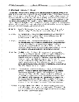
FET Series Power Amplifiers About the FET Series Amps Section 3 Switch Setting Table The following table describes the action of the accessory group switches. The switch positions (left or right) are as viewed from the rear of the amp. Where the action of the switch is the same for both channels (-2 through -7) the Channel 1 switch is listed with the channel 2 switch shown in parenthesis beside it. Switch No. Position Function S1-1 & S2-1 Left Configures the amp inputs for normal stereo input. S1-1 & S2-1 Right S1-2 (S2-2) S1-2 (S2-2) S1-3 (S2-3) Left Right Left S1-3 (S2-3) Right S1-4 (S2-4) Left Configures the amp inputs for mono "Y" input operation. (CH 1 and CH2 inputs are "Y"ed together) Both switches must be set either left or right. The CH 1 (CH 2) XLR input ground (pin 1) is lifted (floated). The CH 1 (CH 2) XLR input ground (pin 1) is grounded. Turns on the low cut filter for the channel. This switch cuts the bass below 30 Hz. Turns off the low cut filter for the corresponding channel allowing extended low frequency response. Turns off the high cut filter for the channel. SI-4 (S2-4) SI-5 (S2-5) S1-6 (S2-6) S1-7 (S2-7) S1-8& S2-8 S1-8& S2-8 Right Turns on the high cut filter for the channel. The high cut filter attenuates high frequency material above 25k Hz. Right This switch activates the compressor circuit for the channel. Setting this switch set to the "ON" position with switches -6, and -7 off provides the maximum level of compression and will limit the average output of the amp to about 10% of rated power by providing up to 10 dB of gain reduction. (ALL OTHER COMPRESSOR SWITCHES O1-F) Right Switch S1-5 turns the compressor on and switch S1-6 sets the compression threshold to allow about 6 dB of gain reduction. Output power is limited to about 25% of rated power. (S1-7/S2-7 off) Right Switch S1-5 turns the compressor on and switch S1-7 sets the compression threshold to allow about 3 dB of gain reduction. Output power is limited to about 50% of rated power. (S1-6/S2-6 off) SI-8 LEFT S2-8 RIGHT SI-8 RIGHT S2-8 LEFT This switch configuration provides normal "stereo" operation of the FET amplifier. This switch configuration will place the amplifier in "mono bridged" mode. (Connect input to CH 1 input and connect speakers between the two red binding post terminals. Use CH 1 Level Control) The normal switch settings (as shipped from the factory) are: S1-3: Right, S2-3: Right and S2-8: Right. All other switches are set Left. 3-8
-
 1
1 -
2
-
3
-
4
-
5
-
6
-
7
-
8
-
9
-
10
-
11
-
12
-
13
-
14
-
15
-
16
-
17
-
18
-
19
-
20
-
21
-
22
-
23
-
24
-
25
-
26
-
27
-
 28
28 -
 29
29 -
 30
30 -
 31
31 -
 32
32 -
 33
33 -
 34
34 -
 35
35 -
 36
36 -
 37
37 -
 38
38 -
39
-
40
-
41
-
42
-
43
-
44
-
45
-
46
-
47
-
48
 |
 |
