Casio SA400 User Guide - Page 5
Install Your Sa-400 System, Creating Your Unique System
 |
UPC - 052452704005
View all Casio SA400 manuals
Add to My Manuals
Save this manual to your list of manuals |
Page 5 highlights
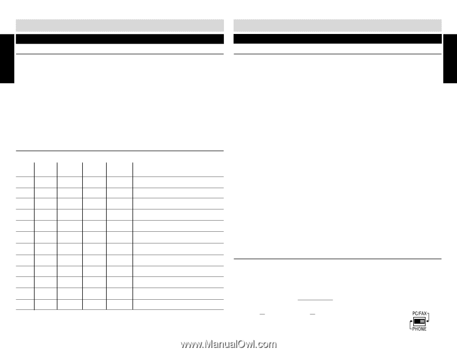
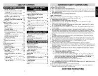
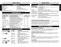
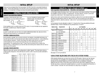
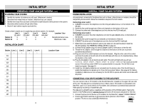
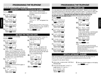
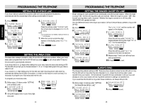
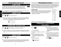
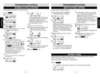
INITIAL SETUP INITIAL SETUP CREATING YOUR UNIQUE SYSTEM (cont.) PLANNING YOUR SYSTEM 1. Identify the number of stations you will need. (Maximum is twelve) 2. Determine how many lines are needed. (Maximum four per station) 3. Identify how many lines you want connected to each Executive Series phone in the system. 4. Determine which stations will get which lines. 5. Decide if each station requires a private line. Create a chart to assist you in organizing your phone system, for example: Line 1: Line 2: Line 3: Line 4: Location / User 111-4567 222-4567 333-4567 444-4567 Station 11 X X X X Receptionist Area / Lisa Station 12 X X X Warehouse / Jake INSTALLATION CHART Station Line 1: - 11 12 13 14 15 16 17 18 19 20 21 22 Line 2: - Line 3: - Line 4: - Location / User 8 INITIAL SETUP INSTALL YOUR SA-400 SYSTEM PHONE INSTALLATION Any equipment connected to the phone line such as faxes, other phones or modems should be temporarily disconnected. Follow the installation sequence for best results. Connecting Lines 1 and 2 1. CONNECT one end of the telephone cord into the jack labeled L1/L2, on the bottom of the SA-400. 2. Guide the line cord through one of the cord channels on the bottom of the unit. 3. Connect the other end of the telephone cord into the two-line RJ14 wall jack. Connecting Lines 3 and 4 4. CONNECT one end of the other telephone cord into the jack labeled L3/L4, on the bottom of the SA-400. 5. Guide the line cord through the cord channels on the bottom of the unit. 6. CONNECT the other end of the telephone cord into the two-line RJ14 wall jack. 7. Determine if you want the phone to set on your desk or to be wall mounted. Install the SA-400 pedestal. See PEDESTAL INSTALLATION on page 41. 8. Connect the AC adapter plug into the AC adapter outlet on the bottom of the SA-400. 9. Thread the AC adapter cord through the channel on the bottom of the unit to prevent accidental disconnection. 10. Plug one end of the coiled handset cord into the handset. Plug the other side of the coiled cord into the outlet on the left side of the SA-400 base with the icon of a handset below. Place the handset in the cradle. 11. Plug the AC adapter into an electrical wall outlet. The LCD will flash and you will see "INITIAL SETUP START". "PRESS START TO SETUP STATION" will scroll across the screen if the soft key under START is not pressed within 15 seconds. The SA-400 is now ready to program. See page 10. 12. Install four AA alkaline batteries (not included) into the bottom side of the SA-400 base to enable the telephone to operate up to 1 hour during a power failure. (See page 42 for battery installation). Batteries are not necessary for the SA-400 to operate and retain stored data with AC power. CONNECTING A FAX OR PC MODEM TO THE DATA PORT You can connect a fax or PC modem to the SA-400 Data Port, located on the upper left rear side of the unit. This data port is connected to line 2. When a fax or PC modem is connected to the Data Port, and it is in use by the fax or PC modem, the connection is protected and cannot be interrupted by incoming or transferred calls. The data port is ALWAYS active, regardless of the position of the PC/FAX switch. Placing the switch in the PC/FAX position silences the ring and turns off line status indication for that line. 1. Connect the line cord of the fax or PC modem into the Data Port, labeled "DOWN STREAM". 2. Position all PC/FAX switches on all Executive Series phones to the PC/FAX position. The line is now a dedicated PC/FAX line. 9 INITIAL SETUP
-
 1
1 -
 2
2 -
 3
3 -
 4
4 -
 5
5 -
 6
6 -
 7
7 -
 8
8 -
 9
9 -
 10
10 -
 11
11 -
12
-
13
-
14
-
15
-
16
-
17
-
18
-
19
-
20
-
21
-
22
-
23
-
24
-
25
-
26
-
27
-
28
-
29
 |
 |