Chamberlain B2212T Installation Manual - English - Page 8
Assembly, STEP 1 Assemble the Rail and Install the Trolley, INSTALLATION, DOOR CONTROL
 |
View all Chamberlain B2212T manuals
Add to My Manuals
Save this manual to your list of manuals |
Page 8 highlights
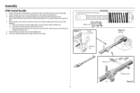
Preparation Hardware ASSEMBLY Bolt Bolt 1/4"-20x1-3/4" Threaded Shaft with Spring Trolley Nut Master Link Hex Screw #8x3/8" (3) Lock Washer 3/8" (packed with the sprocket cover) Nut 3/8" Lock Nut 1/4"-20 INSTALLATION Lag Screw 5/16"-9x1-5/8" (4) Self-Threading Screw 1/4"-14x5/8" (2) DOOR CONTROL Models B2405 and B4505T Drywall Anchors (2) Clevis Pin 5/16"x1-1/2" Hex Bolt 5/16"-18x7/8" (4) Screw 6-32x1" (2) Screw 6ABx1" (2) Clevis Pin 5/16"x1" Clevis Pin 5/16"x1-1/4" Models B2202, B2212T, and B353 Hex Screw 10-24 (2) Wing Nut (2) Nut 5/16"-18 (4) Lock Washer 5/16"-18 (4) Ring Fastener (3) 8 Drywall Anchors (2) Screw 6ABx1-1/2" (2) Insulated Staples (Not Shown)
-
 1
1 -
2
-
 3
3 -
 4
4 -
 5
5 -
 6
6 -
 7
7 -
 8
8 -
 9
9 -
 10
10 -
 11
11 -
 12
12 -
 13
13 -
14
-
15
-
16
-
17
-
18
-
19
-
20
-
21
-
22
-
23
-
24
-
25
-
26
-
27
-
28
-
29
-
30
-
31
-
32
-
33
-
34
-
35
-
36
-
37
-
38
-
39
-
40
-
41
-
42
-
43
-
44
-
45
-
46
-
47
-
48
-
49
-
50
-
51
-
52
 |
 |

8
Hardware
ASSEMBLY
INSTALLATION
Clevis Pin 5/16"x1-1/2"
Ring
Fastener (3)
Hex Bolt 5/16"-18x7/8" (4)
Self-Threading Screw
1/4"-14x5/8" (2)
Clevis Pin 5/16"x1"
Clevis Pin 5/16"x1-1/4"
Hex Screw 10-24 (2)
Wing Nut (2)
Lag Screw 5/16"-9x1-5/8" (4)
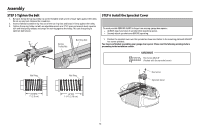
Hex Screw #8x3/8" (3)
(packed with the
sprocket cover)
Bolt 1/4"-20x1-3/4"
Lock Nut
1/4"-20
Bolt
Nut 3/8"
Lock Washer 3/8"
Master Link
Threaded
Shaft with
Spring
Trolley Nut
Lock Washer
5/16"-18 (4)
Nut
5/16"-18 (4)
DOOR CONTROL
Insulated Staples
(Not Shown)
Screw 6ABx1" (2)
Screw
6ABx1-1/2" (2)
Drywall Anchors (2)
Models B2405 and B4505T
Models
B2202, B2212T,
and B353
Drywall
Anchors (2)
Screw 6-32x1" (2)
Preparation