Cisco AIR-BR1310G-A-K9 Hardware Installation Guide - Page 43
Installation Summary - modulator
 |
UPC - 746320927565
View all Cisco AIR-BR1310G-A-K9 manuals
Add to My Manuals
Save this manual to your list of manuals |
Page 43 highlights
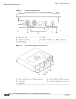
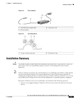
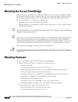
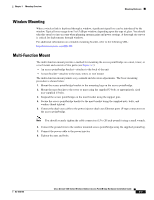
Chapter 2 Installation Overview Figure 2-4 Power Module 3 2 1 Installation Summary 88829 1 48-VDC power output cable 2 Power module Figure 2-5 1 Grounding Block 12 3 AC power cord 88830 1 F-type coaxial connectors Installation Summary 2 Ground wire lug Caution You should read and carefully follow the installation instructions before connecting the system to its power source. The access point/bridge and power injector can be damaged by incorrect power application. Note To meet regulatory restrictions, the external antenna access point/bridge unit and the external antenna must be professionally installed. The network administrator or other IT professional responsible for installing and configuring the unit is a suitable professional installer. Following installation, access to the unit should be password-protected by the network administrator to maintain regulatory compliance. During the installation of the access point/bridge, you will perform the following operations: • Connect a user-supplied Category 5 Ethernet cable from your wired LAN network to the power injector. OL-5048-06 Cisco Aironet 1300 Series Wireless Outdoor Access Point/Bridge Hardware Installation Guide 2-9
-
 1
1 -
2
-
3
-
4
-
5
-
6
-
7
-
8
-
9
-
10
-
11
-
12
-
13
-
14
-
15
-
16
-
17
-
18
-
19
-
20
-
21
-
22
-
23
-
24
-
25
-
26
-
27
-
28
-
29
-
30
-
31
-
32
-
33
-
34
-
35
-
36
-
37
-
 38
38 -
 39
39 -
 40
40 -
 41
41 -
 42
42 -
 43
43 -
 44
44 -
 45
45 -
 46
46 -
 47
47 -
 48
48 -
49
-
50
-
51
-
52
-
53
-
54
-
55
-
56
-
57
-
58
-
59
-
60
-
61
-
62
-
63
-
64
-
65
-
66
-
67
-
68
-
69
-
70
-
71
-
72
-
73
-
74
-
75
-
76
-
77
-
78
-
79
-
80
-
81
-
82
-
83
-
84
-
85
-
86
-
87
-
88
-
89
-
90
-
91
-
92
-
93
-
94
-
95
-
96
-
97
-
98
-
99
-
100
-
101
-
102
-
103
-
104
-
105
-
106
-
107
-
108
-
109
-
110
-
111
-
112
-
113
-
114
-
115
-
116
-
117
-
118
 |
 |
