Cisco VG224 Quick Start Guide - Page 11
Warning, Use copper conductors only., Step 1, - power supply
 |
UPC - 746320575360
View all Cisco VG224 manuals
Add to My Manuals
Save this manual to your list of manuals |
Page 11 highlights
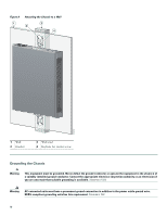
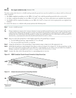
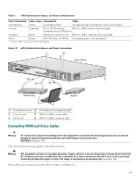
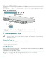
Warning Use copper conductors only. Statement 1025 You must connect the chassis to a reliable earth ground; the ground wire must be installed in accordance with local electrical safety standards. • For NEBS-compliant grounding, use size AWG 6 (13 mm2) wire and the ground lug provided in the accessory kit. • For NEC-compliant grounding, use size AWG 14 (2 mm2) or larger wire and an appropriate user-supplied ring terminal. • For EN/IEC 60950-compliant grounding, use size AWG 18 (1 mm2) or larger wire and an appropriate user-supplied ring terminal. To connect the chassis to a reliable earth ground, perform the following steps: Step 1 Locate a suitable ground. Tip Using a multimeter, measure the resistance between various possible ground locations, such as between the ground of a junction box (outlet) and the ground of a power tap, between the ground of a junction box and a metal water pipe, between the Cisco IAD chassis and the ground of a power tap, and between the Cisco IAD chassis and the ground of a junction box. A good ground connection should read between 0.0 and 0.5 ohms. Step 2 Step 3 Step 4 Step 5 Strip one end of the ground wire to the length required for the ground lug or terminal. • For the NEBS ground lug-approximately 0.75 in. (20 mm) • For user-provided ring terminal-as required Crimp the ground wire to the ground lug or ring terminal, using a crimp tool of the appropriate size. Attach the ground lug or ring terminal to the chassis as shown in Figure 10 or Figure 11. For the ground lug, use the two screws with captive locking washers provided. For a ring terminal, use one of the screws provided. Use a number 2 Phillips screwdriver, and tighten the screws to a torque of 8 to 10 in-lb (0.9 to 1.1 N-m). Connect the other end of the ground wire to a grounding point at your site. Figure 10 NEBS-Compliant Chassis Ground Connection Using Ground Lug 95919 Ground lug VG224-24FXS Figure 11 Chassis Ground Connection Using Ring Terminal 103513 Ring terminal attachment VG224-24FXS 11
-
 1
1 -
2
-
3
-
4
-
5
-
 6
6 -
 7
7 -
 8
8 -
 9
9 -
 10
10 -
 11
11 -
 12
12 -
 13
13 -
 14
14 -
 15
15 -
 16
16 -
17
-
18
-
19
-
20
 |
 |
