Cisco WS-C3560E48PDSF-RF Hardware Installation Guide - Page 105
Wiring the DC-Input Power Source
 |
UPC - 882658132667
View all Cisco WS-C3560E48PDSF-RF manuals
Add to My Manuals
Save this manual to your list of manuals |
Page 105 highlights
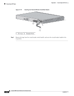
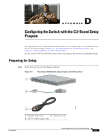
Appendix C Connecting to DC Power Connecting to DC Power Wiring the DC-Input Power Source Warning Before performing any of the following procedures, ensure that power is removed from the DC circuit. Statement 1003 Warning Only trained and qualified personnel should be allowed to install, replace, or service this equipment. Statement 1030 Caution You must connect the Catalyst 3560V2-24TS-SD switch only to a DC-input power source that has an input supply voltage from -36 to -72 VDC. If the supply voltage is not in this range, the switch might not operate properly or might be damaged. Caution The switch must be installed with 5 A-branch-circuit protection. Note This installation must comply with all applicable codes. To wire the switch to a DC-input power source, follow these steps: Step 1 Apply tape to the circuit-breaker switch handle, and move the circuit-breaker handle to the off position. Step 2 Locate and remove the terminal block plug (see Figure C-5). Figure C-5 Terminal Block Plug 60530 Step 3 Step 4 Identify the positive and negative feed positions for the terminal block connection. The wiring sequence is positive to positive and negative to negative for both the A and the B feed wires. The switch rear panel identifies the positive and negative positions for both the A and B feed wires. Using a 18-gauge wire-stripping tool, strip each of the four wires coming from the DC-input power source to 0.27 inch (6.6 mm) ± 0.02 inch (0.5 mm), as shown in Figure C-6. Do not strip more than 0.29 inch (7.4 mm) of insulation from the wire. Stripping more than the recommended amount of wire can leave exposed wire from the terminal block plug after installation. OL-6337-07 Catalyst 3560 Switch Hardware Installation Guide C-5
-
 1
1 -
2
-
3
-
4
-
5
-
6
-
7
-
8
-
9
-
10
-
11
-
12
-
13
-
14
-
15
-
16
-
17
-
18
-
19
-
20
-
21
-
22
-
23
-
24
-
25
-
26
-
27
-
28
-
29
-
30
-
31
-
32
-
33
-
34
-
35
-
36
-
37
-
38
-
39
-
40
-
41
-
42
-
43
-
44
-
45
-
46
-
47
-
48
-
49
-
50
-
51
-
52
-
53
-
54
-
55
-
56
-
57
-
58
-
59
-
60
-
61
-
62
-
63
-
64
-
65
-
66
-
67
-
68
-
69
-
70
-
71
-
72
-
73
-
74
-
75
-
76
-
77
-
78
-
79
-
80
-
81
-
82
-
83
-
84
-
85
-
86
-
87
-
88
-
89
-
90
-
91
-
92
-
93
-
94
-
95
-
96
-
97
-
98
-
99
-
 100
100 -
 101
101 -
 102
102 -
 103
103 -
 104
104 -
 105
105 -
 106
106 -
 107
107 -
 108
108 -
 109
109 -
 110
110 -
111
-
112
-
113
-
114
-
115
-
116
-
117
-
118
-
119
-
120
 |
 |