Cisco WS-C3560E48PDSF-RF Hardware Installation Guide - Page 45
Attaching the RPS Connector Cover,
 |
UPC - 882658132667
View all Cisco WS-C3560E48PDSF-RF manuals
Add to My Manuals
Save this manual to your list of manuals |
Page 45 highlights
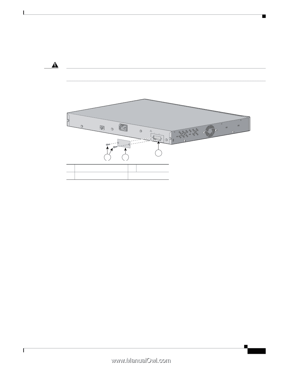
Chapter 2 Switch Installation (24- and 48-Port Switches) Installing the Switch Attaching the RPS Connector Cover If you are not using an RPS with your switch, use the two Phillips pan-head screws to attach the RPS connector cover to the back of the switch, as shown in Figure 2-11. Warning If a redundant power system (RPS) is not connected to the switch, install an RPS connector cover on the back of the switch. Statement 265 Figure 2-11 Attaching the RPS Connector Cover on the Catalyst 3560 Switch 97926 CONSOLE 5.0A1-20R.05A-A2T,0IN500GV-6~0 HZ [email protected]@YMUO7A.TL8EA 3 1 2 1 Phillips pan-head screws 3 RPS connector 2 RPS connector cover OL-6337-07 Catalyst 3560 Switch Hardware Installation Guide 2-13
-
 1
1 -
2
-
3
-
4
-
5
-
6
-
7
-
8
-
9
-
10
-
11
-
12
-
13
-
14
-
15
-
16
-
17
-
18
-
19
-
20
-
21
-
22
-
23
-
24
-
25
-
26
-
27
-
28
-
29
-
30
-
31
-
32
-
33
-
34
-
35
-
36
-
37
-
38
-
39
-
 40
40 -
 41
41 -
 42
42 -
 43
43 -
 44
44 -
 45
45 -
 46
46 -
 47
47 -
 48
48 -
 49
49 -
 50
50 -
51
-
52
-
53
-
54
-
55
-
56
-
57
-
58
-
59
-
60
-
61
-
62
-
63
-
64
-
65
-
66
-
67
-
68
-
69
-
70
-
71
-
72
-
73
-
74
-
75
-
76
-
77
-
78
-
79
-
80
-
81
-
82
-
83
-
84
-
85
-
86
-
87
-
88
-
89
-
90
-
91
-
92
-
93
-
94
-
95
-
96
-
97
-
98
-
99
-
100
-
101
-
102
-
103
-
104
-
105
-
106
-
107
-
108
-
109
-
110
-
111
-
112
-
113
-
114
-
115
-
116
-
117
-
118
-
119
-
120
 |
 |
2-13
Catalyst 3560 Switch Hardware Installation Guide
OL-6337-07
Chapter 2
Switch Installation (24- and 48-Port Switches)
Installing the Switch
Attaching the RPS Connector Cover
If you are not using an RPS with your switch, use the two Phillips pan-head screws to attach the
RPS connector cover to the back of the switch, as shown in
Figure 2-11
.
Warning
If a redundant power system (RPS) is not connected to the switch, install an RPS connector cover on
the back of the switch.
Statement 265
Figure 2-11
Attaching the RPS Connector Cover on the Catalyst 3560 Switch
1
Phillips pan-head screws
3
RPS connector
2
RPS connector cover
97926
RATING
100-200V ~
5.0A-2.5A, 50-60 HZ
CONSOLE
DC INPUTS FOR REMOTE
POWER SUPPLY
SPECIFIED IN MANUAL
+12v
@7.5A -48
@7.8A
2
3
1