Cisco WS-C3560E48PDSF-RF Hardware Installation Guide - Page 44
Wall-Mounting, Attaching the Brackets to the Switch for Wall Mounting,
 |
UPC - 882658132667
View all Cisco WS-C3560E48PDSF-RF manuals
Add to My Manuals
Save this manual to your list of manuals |
Page 44 highlights
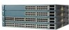
Installing the Switch Chapter 2 Switch Installation (24- and 48-Port Switches) Wall-Mounting These switches wall-mount only with the front panel facing up: • Catalyst 3560-24PS, 3560-24TS-S, 3560-48PS, and 3560-48TS-S • Catalyst 3560G-24PS, 3560G-24TS, 3560G-48PS, and 3560G-48TS These switches wall-mount with the front panel facing up or down: • Catalyst 3560V2-24PS, 3560V2-24TS, 3560V2-48PS, and 3560V2-48TS The illustrations in this section show the Catalyst 3560G-48PS switch as an example. Caution You must install the RPS connector cover before wall-mounting the switch. Warning Read the wall-mounting instructions carefully before beginning installation. Failure to use the correct hardware or to follow the correct procedures could result in a hazardous situation to people and damage to the system. Statement 378 To install the switch on a wall, follow the instructions in these procedures: • Attaching the Brackets to the Switch for Wall Mounting, page 2-12 • Attaching the RPS Connector Cover, page 2-13 • Mounting the Switch on a Wall, page 2-14 Attaching the Brackets to the Switch for Wall Mounting Figure 2-10 shows how to attach a 19-inch bracket to one side of the switch. Follow the same steps to attach the second bracket to the opposite side. Figure 2-10 Attaching the 19-inch Brackets for Wall Mounting 97925 40 41 42 43 44 45 46 47 48 47X Catalyst 3560 SERIES PoE-48 1 3 48X 2 4 1 1 Phillips truss-head screws 2-12 Catalyst 3560 Switch Hardware Installation Guide OL-6337-07
-
 1
1 -
2
-
3
-
4
-
5
-
6
-
7
-
8
-
9
-
10
-
11
-
12
-
13
-
14
-
15
-
16
-
17
-
18
-
19
-
20
-
21
-
22
-
23
-
24
-
25
-
26
-
27
-
28
-
29
-
30
-
31
-
32
-
33
-
34
-
35
-
36
-
37
-
38
-
 39
39 -
 40
40 -
 41
41 -
 42
42 -
 43
43 -
 44
44 -
 45
45 -
 46
46 -
 47
47 -
 48
48 -
 49
49 -
50
-
51
-
52
-
53
-
54
-
55
-
56
-
57
-
58
-
59
-
60
-
61
-
62
-
63
-
64
-
65
-
66
-
67
-
68
-
69
-
70
-
71
-
72
-
73
-
74
-
75
-
76
-
77
-
78
-
79
-
80
-
81
-
82
-
83
-
84
-
85
-
86
-
87
-
88
-
89
-
90
-
91
-
92
-
93
-
94
-
95
-
96
-
97
-
98
-
99
-
100
-
101
-
102
-
103
-
104
-
105
-
106
-
107
-
108
-
109
-
110
-
111
-
112
-
113
-
114
-
115
-
116
-
117
-
118
-
119
-
120
 |
 |
