Compaq ProLiant 6400R Compaq ProLiant 6400R Servers - Page 133
Connectors, Switches, and LED Indicators
 |
View all Compaq ProLiant 6400R manuals
Add to My Manuals
Save this manual to your list of manuals |
Page 133 highlights
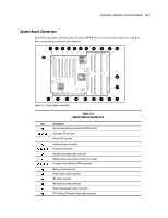
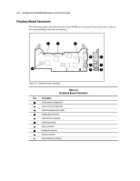
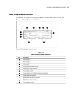
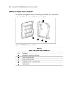
4 Chapter Connectors, Switches, and LED Indicators This chapter provides connector, switch, and LED information for Compaq ProLiant 6400R servers. NOTE: Many of the figures in this chapter show the external rear hot-plug redundant CPU fan. The information in the figures also applies to the external rear hot-plug redundant system fan assembly, unless noted otherwise. Connectors This section contains graphics and tables depicting connector locations on the rear panel, system board, peripheral board, power backplane board, backplane board, and fan controller board. Rear Panel Connectors The following figure and table show ProLiant 6400R Server rear panel connectors and give the corresponding connector descriptions. NOTE: The following illustration only shows the external rear hot-plug redundant CPU fan. Unless noted otherwise, the information provided from this illustration also applies to the external rear hot-plug redundant system fan assembly.
-
 1
1 -
2
-
3
-
4
-
5
-
6
-
7
-
8
-
9
-
10
-
11
-
12
-
13
-
14
-
15
-
16
-
17
-
18
-
19
-
20
-
21
-
22
-
23
-
24
-
25
-
26
-
27
-
28
-
29
-
30
-
31
-
32
-
33
-
34
-
35
-
36
-
37
-
38
-
39
-
40
-
41
-
42
-
43
-
44
-
45
-
46
-
47
-
48
-
49
-
50
-
51
-
52
-
53
-
54
-
55
-
56
-
57
-
58
-
59
-
60
-
61
-
62
-
63
-
64
-
65
-
66
-
67
-
68
-
69
-
70
-
71
-
72
-
73
-
74
-
75
-
76
-
77
-
78
-
79
-
80
-
81
-
82
-
83
-
84
-
85
-
86
-
87
-
88
-
89
-
90
-
91
-
92
-
93
-
94
-
95
-
96
-
97
-
98
-
99
-
100
-
101
-
102
-
103
-
104
-
105
-
106
-
107
-
108
-
109
-
110
-
111
-
112
-
113
-
114
-
115
-
116
-
117
-
118
-
119
-
120
-
121
-
122
-
123
-
124
-
125
-
126
-
127
-
 128
128 -
 129
129 -
 130
130 -
 131
131 -
 132
132 -
 133
133 -
 134
134 -
 135
135 -
 136
136 -
 137
137 -
 138
138 -
139
-
140
-
141
-
142
-
143
-
144
-
145
-
146
-
147
-
148
-
149
-
150
-
151
-
152
-
153
-
154
-
155
-
156
-
157
-
158
-
159
-
160
-
161
-
162
-
163
-
164
-
165
-
166
-
167
-
168
-
169
-
170
-
171
-
172
-
173
 |
 |
