Craftsman 16781 Owners Manual - Page 10
To Set Up Your Unit
 |
View all Craftsman 16781 manuals
Add to My Manuals
Save this manual to your list of manuals |
Page 10 highlights
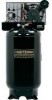
Contents of Carton 1 - Air Compressor 1 - Parts bag containing: 1 - Owner's Manual 4 - 5/8" Washers 1 - Conduit Connector Tools Required for Assembly 1 - 9/16" socket or open end wrench 1 - Electric drill Unpacking 1. Remove all packaging. __l_t to mbaraycebeornescuepspsoarrty one side of the outfit when removing the pallet because the air compressor will have a tendency to tip. 2. Remove and discard the (4) screws and washers holding the compressor to the pallet. 3. With the help of another person carefully remove air compressor from pallet and place on a level surface. _This shippceodmpwreitshsoroil inwas the pump crankcase. Check oil before operating air compressor, see Check Oil under Maintenance. HOW TO SET UP YOUR UNIT Location of the Air Compressor • Locate the air compressor in a clean, dry, and well ventilated area. Located the air compressor at least 12" (30.5 cm) away from the wall or other obstructions that will interfere with the flow of air. Locate the air compressor as close to the main power supply as possible to avoid using long lengths of electrical wiring. NOTE: Long lengths of electrical wiring could cause power loss to the motor. The air filter must be kept clear of obstructions which could reduce air flow to the air com- presso£ Anchoring of the Air Compressor _Risk ExcesosfiveBursting. Vibration can weaken the air tank and cause an explosion. The compressor must be properly mounted. The air compressor MUST be bolted to a solid, level surface. Hardware needed: 4 - Concrete anchors (not supplied) 4 - 3/8" Lag screw to fit concrete anchors (not supplied) 4 - 5/8" Washer (supplied) shims (if needed) 1. Place the air compressor on a solid, level surface. 2. Mark the surface using the holes in the air compressor feet as a template. 3. Drill holes in the surface for the concrete anchors. Install concrete anchors. 4. Line-up holes in surface with holes in air compressor feet. 5. Place the (4) washers (supplied) between the floor and air com- pressor feet. If needed, solid shims may be placed between the washers and floor to evenly distribute weight on all four feet. See next figure. 1000002023 10 ENG
-
 1
1 -
2
-
3
-
4
-
 5
5 -
 6
6 -
 7
7 -
 8
8 -
 9
9 -
 10
10 -
 11
11 -
 12
12 -
 13
13 -
 14
14 -
 15
15 -
16
-
17
-
18
-
19
-
20
-
21
-
22
-
23
-
24
-
25
-
26
-
27
-
28
-
29
-
30
-
31
-
32
-
33
-
34
-
35
-
36
-
37
-
38
-
39
-
40
-
41
-
42
-
43
-
44
-
45
-
46
-
47
-
48
-
49
-
50
-
51
-
52
 |
 |
