Craftsman 16781 Owners Manual - Page 19
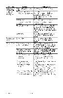
Exhaust, Valves, Inspect, Lines, Fittings, Leaks, Compressor, Bolts, Torquing, Operation.,
 |
View all Craftsman 16781 manuals
Add to My Manuals
Save this manual to your list of manuals |
Page 19 highlights
1. Turn air compressor off, lock out the power supply, and relieve all air pressure from the air tank. 2. Remove belt guard. 3. Place a straightedge against the outside of the flywheel and the motor drive pulley. 4. Measure the distance between the edge of the belt and the straightedge at points A1 and A2 in figure. The difference between measurements should be no more than 1/16" (1.6 mm). 5. If the difference is greater than 1/16" (1.6 mm) loosen the set screw holding the motor drive pulley to the shaft and adjust the pulley's position on the shaft until the A1 and A2 measurements are within 1/16" (1.6 mm) of each other. 6. Tighten the motor drive pulley set screw. See Parts manual for torque specifications. 7. Visually inspect the motor drive pulley to verify that it is perpendicular to the drive motor shaft. Points B1 and B2 of Figure should appear to be equal. If they are not, loosen the setscrew of the motor drive pulley and equalize B1 and B2, using care not to disturb the belt alignment performed in step 2. 8. Retighten the motor drive pulley setscrew. See Parts manual for torque specifications. 9. Reinstall belt guard. AIR COMPRESSOR PUMP iNTAKE AND EXHAUST VALVES Once a year have a Trained Service Technician check the air compressor pump intake and exhaust valves. iNSPECT AIR LINES AND FITTINGS FOR LEAKS 1. Turn air compressor off, lock out the power supply, and relieve all air pressure from the air tank. 2. Apply a soap solution to all air line fittings and connections/piping. 3. Correct any leaks found. IMPORTANT: Even minor leaks can cause the air compressor to overwork, resulting in premature breakdown or inadequate performance. AIR COMPRESSOR HEAD BOLTS = TORQUING The air compressor pump head bolts should be kept properly torqued. Check the torques of the head bolts after the first five hours of operation. Retighten if necessary. See Parts List for torque specifications. ALL MAINTENANCE AND REPAIR OPERATIONS NOT LISTED MUST BE PERFORMED BY TRAINED SERVICE TECHNICIAN. _Risk OperaotifonU.nsaUfneit cycles automatically when power is on. When servicing, you may be exposed to voltage sources, compressed air, or moving parts. Before servicing unit unplug or disconnect electrical supply to the air compressor, bleed tank of pressure, and allow the air compressor to cool. TO REPLACE OR CLEAN CHECK VALVE 1. Release all air pressure from air tank. See "To Drain Tank" in the Maintenance section. 2. Turn air compressor off, lock out the power supply, and relieve all air pressure from the air tank. 3. Using an adjustable wrench loosen outlet tube nut at air tank and pump. Carefully move outlet tube away from check valve. 19 ENG 1000002023
-
 1
1 -
2
-
3
-
4
-
5
-
6
-
7
-
8
-
9
-
10
-
11
-
12
-
13
-
 14
14 -
 15
15 -
 16
16 -
 17
17 -
 18
18 -
 19
19 -
 20
20 -
 21
21 -
 22
22 -
 23
23 -
 24
24 -
25
-
26
-
27
-
28
-
29
-
30
-
31
-
32
-
33
-
34
-
35
-
36
-
37
-
38
-
39
-
40
-
41
-
42
-
43
-
44
-
45
-
46
-
47
-
48
-
49
-
50
-
51
-
52
 |
 |
