Craftsman 21237 Operation Manual - Page 10
Ia Warning - sliding miter saw
 |
View all Craftsman 21237 manuals
Add to My Manuals
Save this manual to your list of manuals |
Page 10 highlights
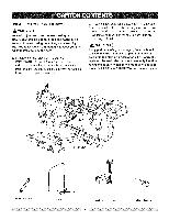
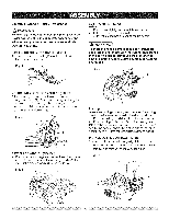
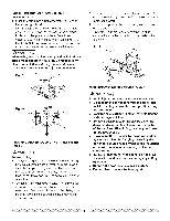
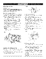
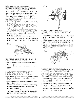
Estimated Assembly Time: 5 - 10 minutes [,AWAR"I"GI To avoid injury, do not connect this miter saw to the power source until it is completely assembled and adjusted and you have read and understood this Operator's Manual. iNSTALLiNG THE MITER HANDLE (FIG. A) 1 Thread the miter handle (1) into the hole located at the front of the miter table. Fig. A CUTTING HEAD (FIG. C) Raising 1. Push down slightly on the switch handle (I). 2. Pull out the stop latch knob (2). 3. Allow the cutting head to rise to the up position. IA WARNINGI To avoid injury and damage to the saw, transport and store the miter saw with the cutting head locked in the down position. Never use the stop latch to hold the cutting head in a down position for cutting operations. Fig, C UNLOCKING THE SLIDE CARRIAGE (FIG. B) After removing the saw from the carton, loosen the slide carriage lock knob (1). When transporting or storing the miter saw, the slide carriage should always be locked in position. The slide carriage lock knob (1) is located on the bottom of the slide carriage. Fig. B SAW BLADE WRENCH (FIG. B-l) 1. For convenient storage and prevention of loss, there is a slot (1) in the rear of the carrying handle (2) for storing the blade wrench (3) when not in use. Fig. B-1 3I 2 Locking When transporting or storing the miter saw, the cutting head should always be locked in the down position. 1. Push the cutting head down to its lowest position. 2. Push the stop latch knob (2) into the locking hole. IMPORTANT: To avoid damage, never carry the miter saw by the switch handle, the cutting arm or the miter handle. ALWAYS use the designated carrying handle. iNSTALLiNG THE DUST BAG (FIG. D) 1. Squeeze the metal collar wings (2) of the dust bag (1). 2. Place the dust bag neck opening around the exhaust port (3), and release the metal collar wings. Fig. D I 2 10
-
 1
1 -
2
-
3
-
4
-
 5
5 -
 6
6 -
 7
7 -
 8
8 -
 9
9 -
 10
10 -
 11
11 -
 12
12 -
 13
13 -
 14
14 -
 15
15 -
16
-
17
-
18
-
19
-
20
-
21
-
22
-
23
-
24
-
25
-
26
-
27
-
28
-
29
-
30
 |
 |
