Craftsman 21237 Operation Manual - Page 14
Warnnng
 |
View all Craftsman 21237 manuals
Add to My Manuals
Save this manual to your list of manuals |
Page 14 highlights
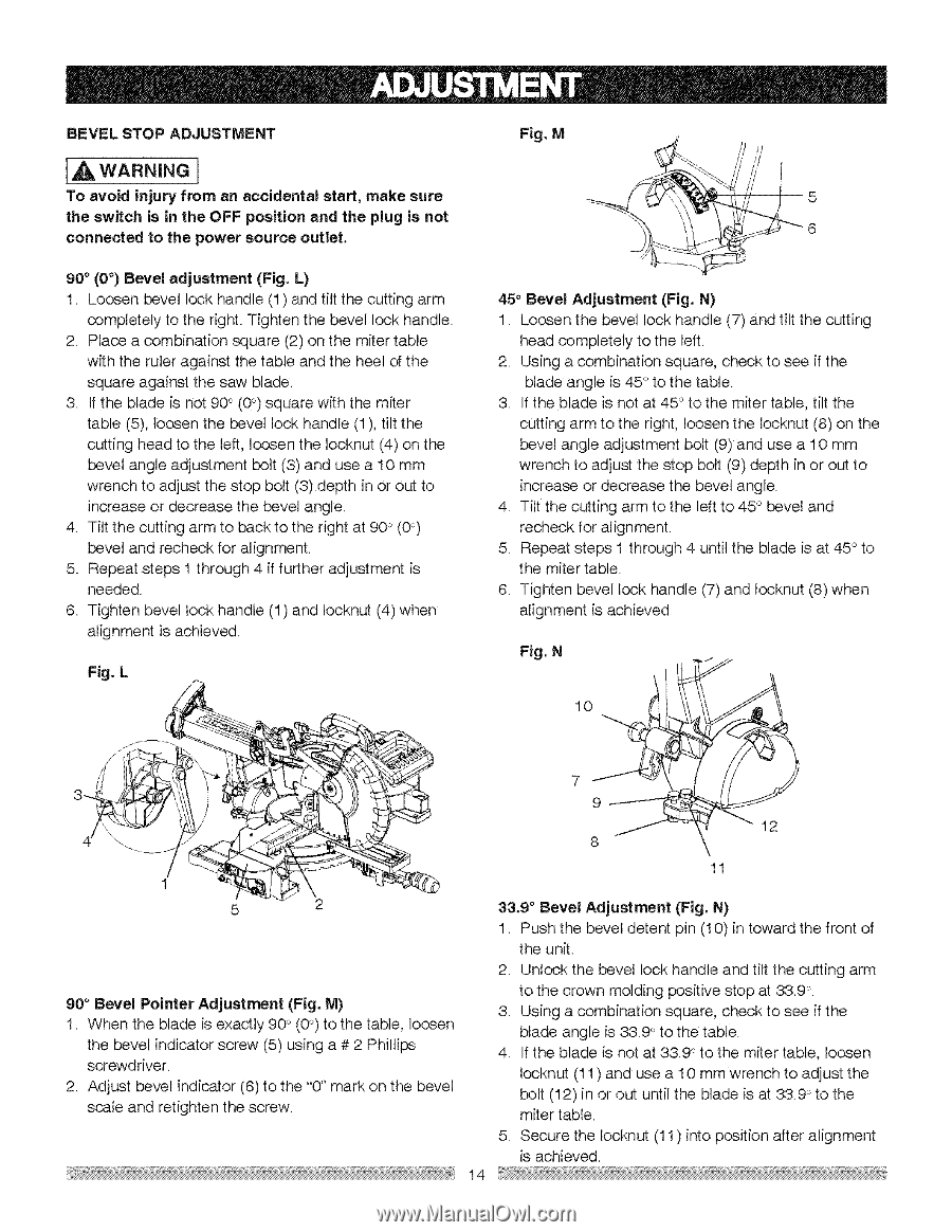
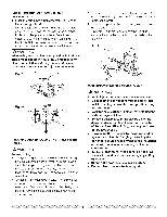
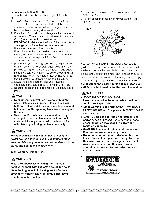
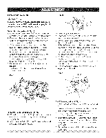
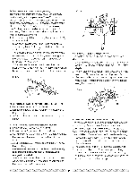
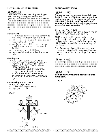
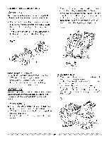
BEVEL STOP ADJUSTMENT [4 WARNNING To avoid injury from an accidental start, make sure the switch is in the OFF position and the plug is not connected to the power source outlet. Fig. M y 5 6 90 ° (0 °) Bevel adjustment (Fig. L) I. Loosen bevel lock handle (1) and tilt the cutting arm completely to the right. Tighten the bevel lock handle. 2. Place a combination square (2) on the miter table with the ruler against the table and the heel of the square against the saw blade. 3. If the blade is not 90 ° (0°) square with the miter table (5), loosen the bevel lock handle (I), tilt the cutting head to the left, loosen the Iocknut (4) on the bevel angle adjustment bolt (3) and use a 10 mm wrench to adjust the stop bolt (3) depth in or out to increase or decrease the bevel angle. 4 Tilt the cutting arm to back to the right at 90 _'(0°) bevel and recheck for alignment. 5. Repeat steps 1 through 4 if further adjustment is needed. 6 Tighten bevel lock handle (1) and Iocknut (4) when alignment is achieved. Fig. L 45 ° Bevel Adjustment (Fig. N) 1. Loosen the bevel lock handle (7) and tilt the cutting head completely to the left. 2. Using a combination square, check to see if the blade angle is 45 ° to the table. 3. If the blade is not at 45 ° to the miter table, tilt the cutting arm to the right, loosen the Iocknut (8) on the bevel angle adjustment bolt (9) and use a 10 mm wrench to adjust the stop bolt (9) depth in or out to increase or decrease the bevel angle. 4. Tilt the cutting arm to the left to 45 ° bevel and recheck for align ment. 5. Repeat steps 1 through 4 until the blade is at 45 ° to the miter table. 6. Tighten bevel lock handle (7) and Iocknut (8) when alignment is achieved Fig. N 10 i 79_---- i J 12 8 1 5 2 90 ° Bevel Pointer Adjustment (Fig. M) 1. When the blade is exactly 90 °`(0°) to the table, loosen the bevel indicator screw (5) using a # 2 Phillips screwdriver. 2. Adjust bevel indicator (6) to the "0" mark on the bevel scale and retighten the screw. 11 33.9 ° Bevel Adjustment (Fig. N) 1. Push the bevel detent pin (10) in toward the front of the unit. 2. Unlock the bevel lock handle and tilt the cutting arm to the crown molding positive stop at 33.9 ° 3. Using a combination square, check to see if the blade angle is 33.90 to the table. 4. If the blade is not at 33.90 to the miter table, loosen Iocknut (11 ) and use a 10 mm wrench to adjust the bolt (12) in or out until the blade is at 33.9 ° to the miter table. 5. Secure the Iocknut (11 ) into position after alignment is achieved. 14
-
 1
1 -
2
-
3
-
4
-
5
-
6
-
7
-
8
-
 9
9 -
 10
10 -
 11
11 -
 12
12 -
 13
13 -
 14
14 -
 15
15 -
 16
16 -
 17
17 -
 18
18 -
 19
19 -
20
-
21
-
22
-
23
-
24
-
25
-
26
-
27
-
28
-
29
-
30
 |
 |