Craftsman 21829 Operation Manual - Page 18
Bevel, Handle
 |
View all Craftsman 21829 manuals
Add to My Manuals
Save this manual to your list of manuals |
Page 18 highlights
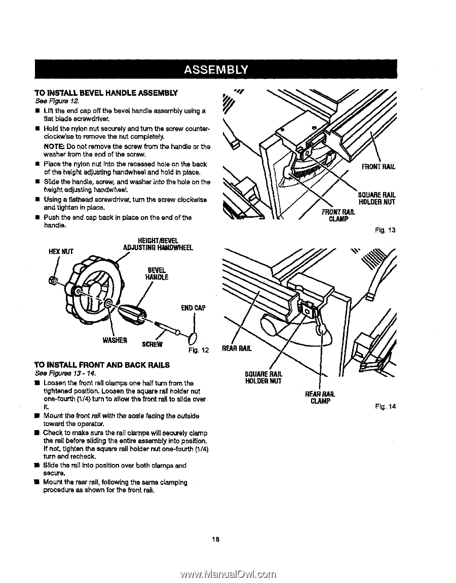
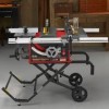
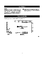
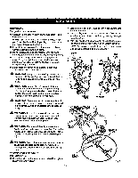
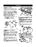
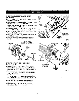
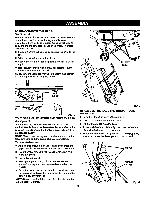
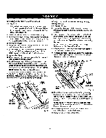
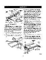
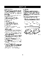
TO IN_rALL BEVEL HANDLE ASSEMBLY See F-t_re 12. • Lift the end rap offthe bevel handle assembly usinga fiat b|ade screwdriver, • Hold the nylonnut securelyand turn the screw counterclockwise toremove thenutcompletely. NOTE: Do not remove the screw from the handle or the washer from the end of the screw. • Place the nylon nut into the recessed holeon the back of the height adjustinghandwheel and hold in place, • Slide the handle,screw, and washer into the hole on the he(ghtadjustlnl_9n_'_heaL • Using a fiathead screwdriver, turn the screw clockwise and tighteinnplace. • Push the end cap back in place on the end of the handle. HEXNUT HEIGHT/BEVEL ADJUSTINGRANDWHEEL BEVEL HANDLE FRONTPAIL SQUARERAIL HOLDERNUT WONTRAIL cLAMP Fig. 1"3 WASHER TO INSTALL FRONT AND BACK RAILS See Figures 13 - 14, • Loosenthe frontrail ciarnps one half turn fi'omthe tightened position. Loosen the square ragholder nut one-fourth (1/4t)urn"_oallowthe front ra_to slide ovsr it. • Mount the _ontrailwith thescale faoincj the outside toward the operator. • Check to make sure the rail clamps will securelyclamp the rai( before slidingthe entire assembly into position. If not, tighten the square rail holder nut one-fourth (1/4) turn and recheck. • Slide the rail into position over both clamps and secure. • Mount the rear rail, following the same ciamping procedure as shown for the front rail SQUARERAIL HOLDERNUT REARRAIL CLAMP Fig. 14 18
-
 1
1 -
2
-
3
-
4
-
5
-
6
-
7
-
8
-
9
-
10
-
11
-
12
-
 13
13 -
 14
14 -
 15
15 -
 16
16 -
 17
17 -
 18
18 -
 19
19 -
 20
20 -
 21
21 -
 22
22 -
 23
23 -
24
-
25
-
26
-
27
-
28
-
29
-
30
-
31
-
32
-
33
-
34
-
35
-
36
-
37
-
38
-
39
-
40
-
41
-
42
-
43
-
44
-
45
-
46
-
47
-
48
-
49
-
50
-
51
-
52
-
53
-
54
-
55
-
56
-
57
-
58
 |
 |