Craftsman 21829 Operation Manual - Page 37
Accessory, Table Usage
 |
View all Craftsman 21829 manuals
Add to My Manuals
Save this manual to your list of manuals |
Page 37 highlights
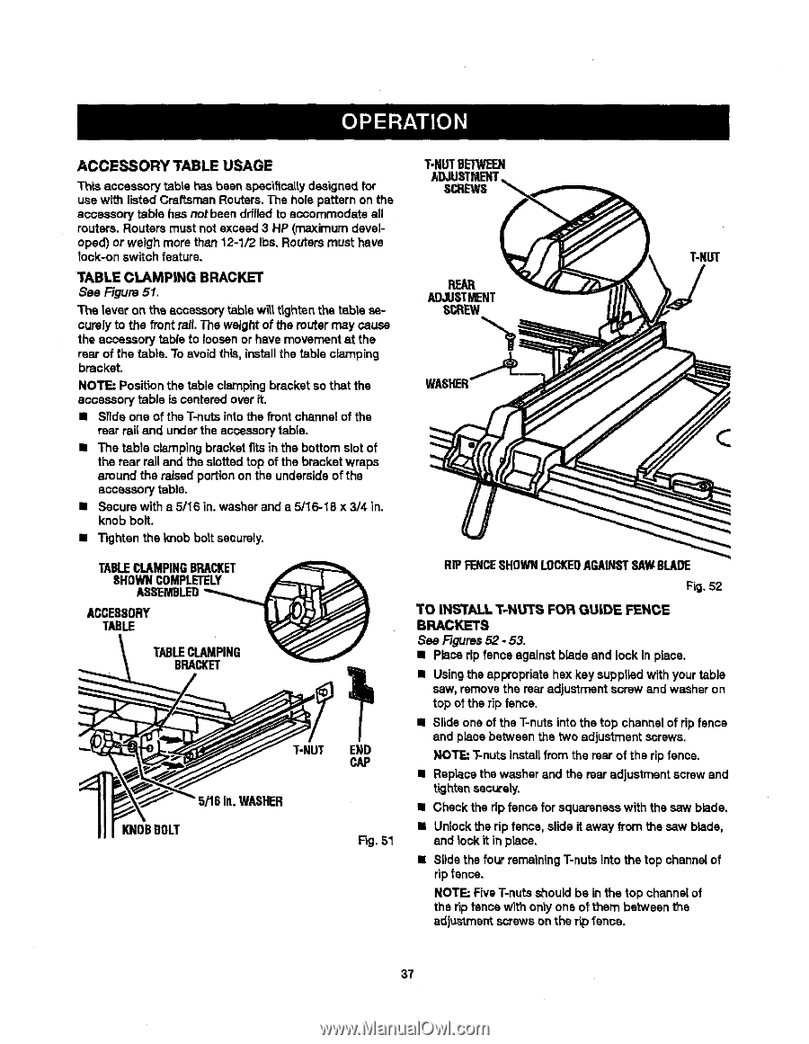
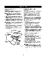
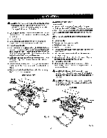
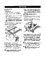
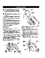
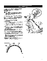
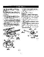
ACCESSORY TABLE USAGE Th|s accessory table has been spec'dtcaltydesignedfor use with listed Craftsmen Routars.The hole pattern on the accessory table has notbeen drfflad to accommodate all reuters. Reuters must not exceed 3 HP (maximum developed) or weigh more than 12-1/2 Ibs. Reutersmust have took-on switch feature. TABLE CLAMP|NG BRACKET See Figure 51. The lever on the accessory table wilt.tighten the table securelyto the front rail. The weight of the muter may cause the accessory table to loosen or have movement st the rear of the table. To avoid this, install the table clamping bracket. NOTE: Positionthe table clampingbracket so that the accessory table is centeredover it. II Slide one of the T-nuts into the front channel of the rear rail and under the aooeseorytable. • The table clamping bracket fits in the bottom slot of the rear railand the slotted top of the bracket wraps around the raised portion on the undersideof the accessory table. • Secure wlth a 5/16 in. washer and a 5/16-18 x 3/4 in. knob bolt. • Tighten the knob bolt securely. TABLECLAMPINGBRACKET SHOWNCOMPLETELY ASSEMBLED__,._ ACCESSORY T,.E TABLECLAMPING BRACKET _ L L_L)_ T-NUT END CAP _/'16in.WASHER KNOBBOLT Fig. 51 T-NUTBETWEEN ADJUSTMENT SCREWS REAR ADJUSTMENT SCREW RIP FENCESHOWNLOCKEDAGAINSTSAWBLADE Fig, 52 TO INSTALL T-NU'£_ FOR GUIDE FENCE BRACKETS See Figures52.53. • Place rip fence against blade and lock in place, • Usingthe appropriate hex key supplied with your table saw, remove the rear adjustment screw and washer on top of the rip fence. • Slide one of the T-nutsintothe top channel of ripfence and place between the two adjustment screws. NOTE: T-nutsinstallfrom the rear of the rip fence. • Replacethe washer and the rear adjustmentscrew and tighten securely. • Checkthe rip fsncs for squarsnesswith ths saw blade, • Unlock the rip fence, slide it away from the saw blade, and lock it in place, Slidethe four remainingT-nuts into the top channelof ripfence. NOTE: Five T-nuts shouldbe in the top channelof the rip fencewith only one of them between the adjustmentscrews on the rip fence. 37
-
 1
1 -
2
-
3
-
4
-
5
-
6
-
7
-
8
-
9
-
10
-
11
-
12
-
13
-
14
-
15
-
16
-
17
-
18
-
19
-
20
-
21
-
22
-
23
-
24
-
25
-
26
-
27
-
28
-
29
-
30
-
31
-
 32
32 -
 33
33 -
 34
34 -
 35
35 -
 36
36 -
 37
37 -
 38
38 -
 39
39 -
 40
40 -
 41
41 -
 42
42 -
43
-
44
-
45
-
46
-
47
-
48
-
49
-
50
-
51
-
52
-
53
-
54
-
55
-
56
-
57
-
58
 |
 |