Craftsman 21829 Operation Manual - Page 39
Toinstallrouter
 |
View all Craftsman 21829 manuals
Add to My Manuals
Save this manual to your list of manuals |
Page 39 highlights
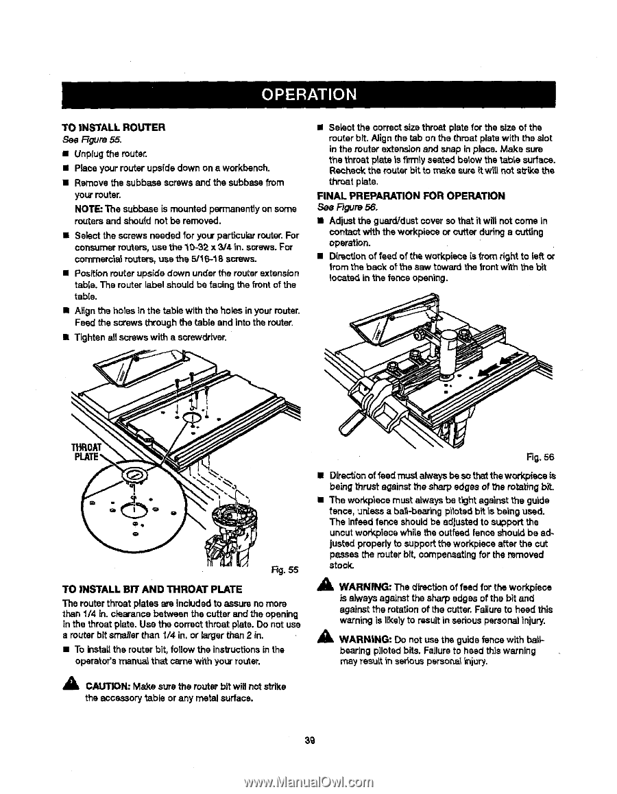
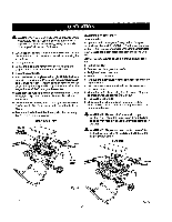
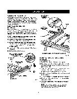
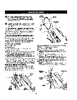
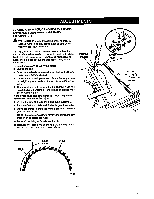
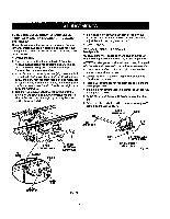
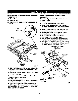
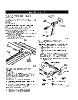
TOINSTALLROUTER See Ftgure55. • Unptugthe router. • Place your router upside down on a workbench. • Remove the subbase screws and the subbasefrom your router. NOTE: The subbase is mounted permanentlyon some routere and should not be removed. • Select the screws needed for yourparticular router.For consumer reuters, use the 10-32 x 3/4 in. screws.For eommerc'la_Pouters,use the 5/16-18 screws. • Positionrouter upside down under the router extension tabie. The router label should be facingthe front of the table. • Atign the holes in the table with the holes in yourrouter. Feed the screws through the table and intothe router. • Tighten all screws with a screwdriver. • Select the correcstize throat plate for the size of the router bit. Align the tab on the throat platewith the slot in the muter extension and snap in place. Make sure the throat plate is firmly seated below the _able surface. Recheck the router bit to make sure it will not s_ke the throat plate. FINAL PREPARATION FOR OPERATION See Figure 56. • Adjust the guard/dustcover so that it will not corns in conta_ with the workplace or cutter duringa cutting operation. • D[rectionof feed of the workplace is from right to left or from the back of t'nesaw toward the frontwith the bit located in the fence opening. \ i Rg. 55 TO INSTALL BIT AND THROAT PLATE The router throat plates are included to assure no more than1/4 in. eisarance between the cutter and the opening in the throat plate. Use the correct throat plate.Do not use a router bit smaller than I/4 in, or larger than 2 in. • To installthe router bit, fotlow the instructionsin the operator'smanua_that came with yourrouter. Fig. 56 • Directionof feed mustalw,_ysbe so thatthe workpiece is being thrust againstthe sharp edges of the foraying bit. • The workp'lecemust alwaysbe tight against _e guide fence, unlessa ba_-bearing pilotedbit is being used. The Infeed fence shouldbe adjusted to support the uncutworkpiees whi_ethe outfeed fence should be adjusted properlyto supportthe workpisce after the cut passes the router bit, compensatingfor the removed stock. 41_ WARNING: The directionof feed for the workpiece is always againstthe sharp edges of the bit and againstthe rotationof the cutter.Fai(uroto heed this warning is I_ely to resultin sedous personalinjury. _i, WARNING: Do not use the guide fencewith ball-bearing pilotedbits. Failureto heed this warning may TesuRin serious peTsonailnjury. _" CAIN: Make sure the router bit will not strike the accessory table or any metal surface. 3g
-
 1
1 -
2
-
3
-
4
-
5
-
6
-
7
-
8
-
9
-
10
-
11
-
12
-
13
-
14
-
15
-
16
-
17
-
18
-
19
-
20
-
21
-
22
-
23
-
24
-
25
-
26
-
27
-
28
-
29
-
30
-
31
-
32
-
33
-
 34
34 -
 35
35 -
 36
36 -
 37
37 -
 38
38 -
 39
39 -
 40
40 -
 41
41 -
 42
42 -
 43
43 -
 44
44 -
45
-
46
-
47
-
48
-
49
-
50
-
51
-
52
-
53
-
54
-
55
-
56
-
57
-
58
 |
 |