Craftsman OR20451 Operation Manual - Page 10
Assembly, Instructions
 |
View all Craftsman OR20451 manuals
Add to My Manuals
Save this manual to your list of manuals |
Page 10 highlights
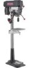
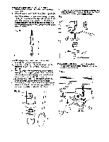
ASSEMBLY INSTRUCTIONS Foryourown safety, neverconnectplug to power sourceoutletuntilall assemblyand adjustmentsteps are completed, and you have read and understood the safetyand operatinginstructions. TOOLS NEEDED Rg. B _ w_encb III t lilt IIIt_ Frw_ing 8" S 10"AdJustab__ Comb_e_m_tre The DdlTPress is very heavy and MUST be liftedwith the helpof 2 PEOPLE OR MORE, to safety assembly it. COLUMN SUPPORT TO BASE (FIG. A) 1. Position the base (1) on the floor. 2. Place the column (2) on the base, aligning the holes in the column support with the holes in the base. 3. Locate the four long hex bolts (3) from the loose parts bag. 4. Place a bolt in each hole through the column support and the base. Tighten with an adjustable wrench. i INSTALLING THE TABLE (FIG. B and C) 1. Locate the table crank (1) and support lock (2) from the loose parts bag. 2. Insert the support lock handle into the hole (3) at the rear of the table support assembly. Tighten by hand. 3. InstaJIthe table crank handle (3) onto the small shaft (4), aligning the set screw (5) with the flat surface of the shaft (4), aligning the set screw (5) with the fiat surface of the shaft. Tighten the set screw with a hex wrench. 4. (FIG. C) Loosen the support lock (2). Raise the table arm assembly by turning the crank handle (1) clockwise. Tighten the support lock. 5. Place the table (6) in the table arm assembly. Tighten the table lock handle (7). Rg. C INSTALLING EXTENSION WING 1. Place the handle (OWVG) onto the upper tube (OWVH). 2. Place the flat washers (OT6T) onto the hex head bolts (OJUB). Insert the bolt (OJUB) into the upper tube (OWVH), and tighten. 3. Insert the hes head bolts (OJUB) onto the upper tube (OJUB) and tighten. 4. Place the upper tube assembly under the table. 5. Place the set plate (OWVJ) onto the clamp bolt (OWVK). Insert the set plate assembly into the table and tighten. NOTE: If length adjustment is necessary, loosen the clamp bolt (OWVK) to the desired length and tighten the clamp bolt. OWVE 10
-
 1
1 -
2
-
3
-
4
-
 5
5 -
 6
6 -
 7
7 -
 8
8 -
 9
9 -
 10
10 -
 11
11 -
 12
12 -
 13
13 -
 14
14 -
 15
15 -
16
-
17
-
18
-
19
-
20
-
21
-
22
-
23
-
24
-
25
-
26
-
27
-
28
-
29
-
30
-
31
-
32
-
33
-
34
-
35
-
36
-
37
-
38
-
39
-
40
-
41
-
42
-
43
-
44
-
45
-
46
-
47
-
48
 |
 |
