Craftsman OR20451 Operation Manual - Page 11
Fig. D, Fig. F
 |
View all Craftsman OR20451 manuals
Add to My Manuals
Save this manual to your list of manuals |
Page 11 highlights
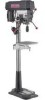
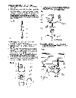
INSTALLING THE HF.AD (FIG. D) mvl/_d_ql K_ The Drill Press h_d Is very heavy and MUST be lifted with the help of 2 PEOPLE OR MORE,to safely assemble the Drill Press head on the column. 1. Carefully lift the head (1) above the column (2) and slide it onto the column.Make sure the head slldea down over the column as far as poealble.Algn the head with the base. 2. Using the hex wrench, tighten the two head lock eat screws (3) on the right side of the head. FENCE ASSEMBLY (FIG. F) This drill press has a channeled table top. 1. Determine the desired location for the fence (1).Sllde theT-blocks (2) Into the appropriate channels as shown 2. Align the mounting holes of the fence over theT-block's threaded hloes. 3. Place a washer (3) on the threaded end of the knob (4). Insert the knob through the mounting hole of the fence into the T-block,and Ugbetan. 4. Repeat for the other knob andT-block. Fig. D Fig. F J"ry _3 INSTALLING FEES HANDLES (FIG. E) 1. Locate three feed handles in the loose parts bag. 2, Screw the feed handles (1) into the threaded holes (2) in the hub (3), Tighten 11
-
 1
1 -
2
-
3
-
4
-
5
-
 6
6 -
 7
7 -
 8
8 -
 9
9 -
 10
10 -
 11
11 -
 12
12 -
 13
13 -
 14
14 -
 15
15 -
 16
16 -
17
-
18
-
19
-
20
-
21
-
22
-
23
-
24
-
25
-
26
-
27
-
28
-
29
-
30
-
31
-
32
-
33
-
34
-
35
-
36
-
37
-
38
-
39
-
40
-
41
-
42
-
43
-
44
-
45
-
46
-
47
-
48
 |
 |
