Craftsman OR20451 Operation Manual - Page 19
Fig. Y
 |
View all Craftsman OR20451 manuals
Add to My Manuals
Save this manual to your list of manuals |
Page 19 highlights
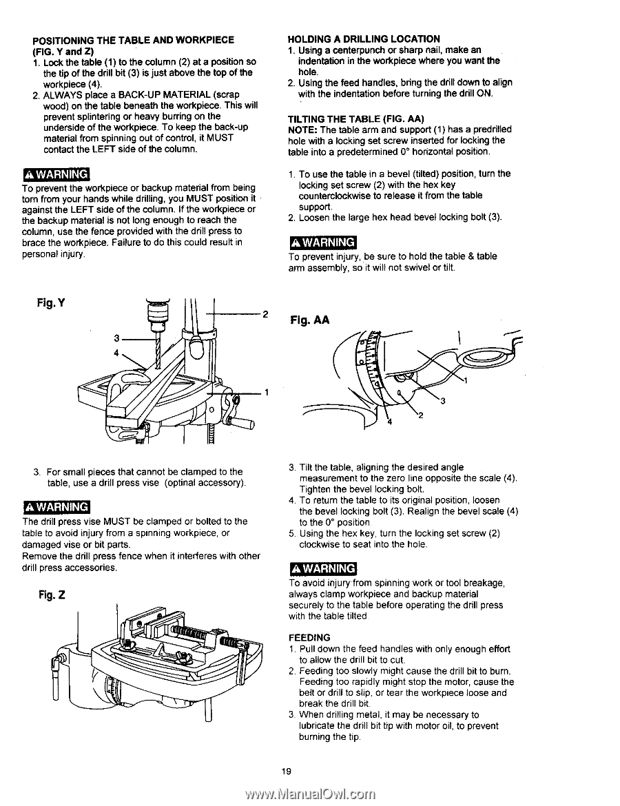
POSITIONING THE TABLE AND WORKPIECE (FIG. Y and Z) 1. Lock the table (1) to the column (2) at a positionso the tip of the drillbit (3) is just above the top of the workpiece(4). 2. ALWAYS place a BACK-UP MATERIAL (scrap wood)on the table beneath the workpiece.This will preventsplinteringor heavy burringon the undersideof the workpiece. To keep the back-up material from spinning out of control, it MUST contact the LEFT side of the column. To prevent the workpiece or backup material from being torn from your hands while drilling, you MUST position it against the LEFT side of the column. If the workpiece or the backup matedal is not long enough to reach the column, use the fence provided with the drill press to brace the workpiece. Failure to do this could result in personal injury. HOLDING A DRILLING LOCATION 1. Using a centerpunchor sharp nail, make an indentationin the workpiece where you want the hole. 2. Using the feed handles,bdng the drilldownto align with the indentationbefore turningthe drillON. TILTING THE TABLE (FIG. AA) NOTE: The table arm and support (1) has a preddlled hole with a locking set screw inserted for locking the table into a predetermined 0 ° horizontal position. 1. To use the table in a bevel (tilted) position, turn the locking set screw (2) with the hex key counterclockwise to release it from the table support. 2. Loosen the large hex head bevel locking bolt (3). _t To prevent injury,be sure to hold the table & table arm assembly, so it will not swivel or tilt. Fig. Y 2 Fig. AA \ 3. For small pieces that cannot be clamped to the table, use a drill press vise (optinal accessory). The drill press vise MUST be clamped or bolted to the table to avoid injury from a spinning workpiece, or damaged vise or bit parts. Remove the drill press fence when it interferes with other drill press accessories. Fig. Z 3. Tilt the table, aligning the desired angle measurement to the zero line opposite the scale (4). Tighten the bevel locking bolt. 4 To return the table to its original position, loosen the bevel locking bolt (3). Realign the bevel scale (4) to the 0° position 5 Using the hex key, turn the locking set screw (2) clockwise to seat into the hole. To avoid injury from spinning work or tool breakage, always clamp workpiece and backup material securely to the table before operating the drill press with the table tilted FEEDING 1. Pull down the feed handles with only enough effort to allow the drill bit to cut. 2 Feeding too slowly might cause the drill bit to burn. Feeding too rapidly might stop the motor, cause the belt or drill to slip, or tear the workpiece loose and break the drill bit 3. When drilling metal, it may be necessary to lubricate the drill bit tip with motor oil, to prevent burning the tip. 19
-
 1
1 -
2
-
3
-
4
-
5
-
6
-
7
-
8
-
9
-
10
-
11
-
12
-
13
-
 14
14 -
 15
15 -
 16
16 -
 17
17 -
 18
18 -
 19
19 -
 20
20 -
 21
21 -
 22
22 -
 23
23 -
 24
24 -
25
-
26
-
27
-
28
-
29
-
30
-
31
-
32
-
33
-
34
-
35
-
36
-
37
-
38
-
39
-
40
-
41
-
42
-
43
-
44
-
45
-
46
-
47
-
48
 |
 |