Craftsman OR20451 Operation Manual - Page 13
Drill Press Adjustments
 |
View all Craftsman OR20451 manuals
Add to My Manuals
Save this manual to your list of manuals |
Page 13 highlights
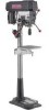
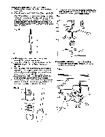
DRILL PRESS ADJUSTMENTS Fig. L CAUTION: All the adjustments for the opera,on of the ddl press have been completed at the lectory.Due to normal wear and use, some occasional madjustmente may be necessary. !_W_,I -'l_l_[el Toprevenptersonainljurya, dys ciscor. thepaufgnxn the powersourcewhen ma;dnganyadjustments SQUARING TABLE TO HEAD (RG. K and L) NOTE: The table arm and support has a preddlledhole with a lockingset screw inserted for lockingthe table to a predetermined0 ° horizontal_. It must be loosened to change the angle of the table. 1. Insert a 1/4", or larger diameter, precisionground stset rod (1), approximately3" long,intothe chuck (2). Tighten the chuck jaws. 2. Raise table to working height and lock. 3. Using the combinationsquare (3), placeena edge fiat on the tebie, and align the other edge verlfoally beside the rod (1). Fig. K 5 6 4 7 BEVEL SCALE (FIG. L and M) NOTE: The bevel scale has been included to measure approximate bevel angles. If precision is necessary, a square or other measuring tool should he used to position the table.To use the bevel scale (7): 1. Loosen the Ioddng set screw (4) to RELEASE it from the table support. 2. Loosen the large hex head bevel locking bolt (6). 2 1 3 III I I I I I I II I [ To prevent injury, be sure to hold the table & table arm assembly, so it will not swivel or tilt. 3. Tilt the table, aligningthe desired angle measurement to the zero line opposite the scale (7). 4. Tighten the bevel lockingbolt. (6). 5. To return the table to its original position, loosen the bevel lockingbolt (6). Realign the bevel scale (7) to the 0 ° position. 6. Tighten the locking set screw (4) until it is seated in the horizontal 0_ hole of the table support. Fig. M 4. If an adjustment is necessary, loosen the lockingset screw (4) with the 3 mm hex key to RELEASE the table from the horizontal position. 5. Loosen the large hex head bevel lockingbolt (6). Tolprevent injury,be sure to hold the table &table arm assembly, so it will not swivel or tilt. 6. Align the square to the red by rotating the table until the square and rod are in line. 7. Retighten the large bex belt. (6). 5 6 7 13
-
 1
1 -
2
-
3
-
4
-
5
-
6
-
7
-
 8
8 -
 9
9 -
 10
10 -
 11
11 -
 12
12 -
 13
13 -
 14
14 -
 15
15 -
 16
16 -
 17
17 -
 18
18 -
19
-
20
-
21
-
22
-
23
-
24
-
25
-
26
-
27
-
28
-
29
-
30
-
31
-
32
-
33
-
34
-
35
-
36
-
37
-
38
-
39
-
40
-
41
-
42
-
43
-
44
-
45
-
46
-
47
-
48
 |
 |
