Craftsman OR20451 Operation Manual - Page 15
Basic Drill Press Opeations
 |
View all Craftsman OR20451 manuals
Add to My Manuals
Save this manual to your list of manuals |
Page 15 highlights
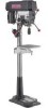
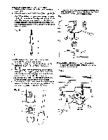
_vlvh_ =1_[I To avoid injury from an accidental start, ALWAYS make sure the switch is in the "OFF" position, the switch key is removed, and the plug is not connected to the power source outlet before making belt adjustments. ALIGNING THE BELT PULLEYS (FIG. N) Open the head cover of the Drill Press. Check alignment of the pulleys with a straight edge (5) such as a framimg square, a level, or a piece of a wood. Lay the straight edge across the top of the pulleys. If all three pulleys are NOT aligned: 1. Release belt pressure by loosening the belt tension lock knobs (4) on either side of the head, unlocking the belt tension handle (1). 2. Loosen the motor mount nuts (2). Lift or lower the motor (3) until the pulleys are in line. 3. Tighten the motor mount nuts (2) using an adjustable wrench. NOTE: To avoid rattles or other noise, the motor housing should not touch the lower belt guard housing. 4. Retighten the belts by turning the belt tension handle (1) clockwise, until the belt deflects approximately 1/2 inch when pressed in the center. NOTE: Refer to the chart inside the belt guard cover for recommended drilling speeds and belt/pulley positions. 5. Lock the belt tension lock knobs (4) by turning clockwise. NOTE: When the belts are new, it may be difficult to move the belts. As the machine is used, the belts will gain more elasticity and will be easier to adjust. BASIC DRILL PRESS OPEATIONS SPEEDS AND BELT PLACEMENT (FIG. R) This drill press has 12 speeds, as listed below: 250 RPM 600 RPM 1620RPM 340 RPM 650 RPM 1900RPM 390 RPM 990 RPM 2620 RPM 510 RPM 1550 RPM 3100RPM See inside of the pulley guard for specific placement of the belts on the pulleys to change speeds. To avoid possible injury, keep guard closed, in place, and in proper working order while tool is in operation. Fig. R 9 9 9 250 trim_ o 9 Q 510 tdmin i 9 9 Fig. Q 9 9 9 3100 tr_lin 14 3 15
-
 1
1 -
2
-
3
-
4
-
5
-
6
-
7
-
8
-
9
-
 10
10 -
 11
11 -
 12
12 -
 13
13 -
 14
14 -
 15
15 -
 16
16 -
 17
17 -
 18
18 -
 19
19 -
 20
20 -
21
-
22
-
23
-
24
-
25
-
26
-
27
-
28
-
29
-
30
-
31
-
32
-
33
-
34
-
35
-
36
-
37
-
38
-
39
-
40
-
41
-
42
-
43
-
44
-
45
-
46
-
47
-
48
 |
 |
