Craftsman OR20451 Operation Manual - Page 9
BELT GUARD ASSEMBLY - Covers the pulleysand
 |
View all Craftsman OR20451 manuals
Add to My Manuals
Save this manual to your list of manuals |
Page 9 highlights
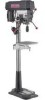
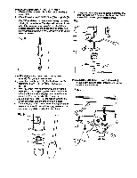
BASE - Supportsdrill press. For additionalstability, holesare provided in base to bolt drillpress to floor. (See "Specific Safety Instruction for Drill Presses.") BACKUP MATERIAL - Apiece of scrap wood placed between the workpiece and table. The backup beard preventswood in the workpiece from splintedngwhen the drillpasses through the backsideof the workpiece. It also prevents drillingintothe table top. BELT GUARD ASSEMBLY - Covers the pulleysand belt duringoperation of the drillpress. BELT TENSION - Refer to the "Assembly" Section, "Installingand Tensioning Belt.". BELT TENSION HANDLE - Turn the handle clockwise to apply tensionto belt, turnthe handle counterclockwise to release belt tension. BELT TENSION LOCK KNOBS - Tighteningthe knobs locks the motor bracket supportand the belt tension handle, maintainingcorrect belt distance and tension. BEVEL SCALE - Shows degree of table tilt for bevel operaions. The scale is mounted on the side of the arm. CHUCK - Holds drill bit or other recommended accessoryto perform desired operations. CHUCK KEY - A self-ejectingchuck key whichwill pop out of the chuck when you let go of it. This actionis designedto help preventthrowing of the chuck key from the chuck when the peer is turned ON. Do not use any other key as a substitute; order a new one if hamaged or lost. COLUMN - Connects the head, table, and base on a one piece tube for easy alignment and movement. COLUMN COLLAR - Holds the rack to the column. Rack remains movable in the collar to permit table support movements. COLUMN SUPPORT - Supports the column, guides the rack and providesmounting holes for column to base. DEPTH SCALE STOP NUTS - Lock the spindle to the selected depth. DEPTH SCALE - Indicates depth of hole being drilled. DRILL BIT - The cutting tool used in the drill press to make holes in a workpiece. DRILL ON/OFF SWITCH - Has lockingfeature. This feature is intended to help prevent unauthorizedand possible hazardous use by children and others. Insert the key into the switch to turn the drill press on. DRILLING SPEED - Changed by placingthe belt in any of the steps (grooves) in the pulleys.See the Spindle Speed Chart inside belt guard. FEED HANDLE - Moves the chuck up or down. IF necessary, one or two of the handles may be removed whenever the workpiece is of such unusualshape that it interfereswith the handles. FENCE - Attaches to the table to alignthe workpiece or for fast repetitivedrilling.Removable. Remove fence when it interfereswith other drillpress accessories. HEAD LOCKS - Locks the head to the column. ALWAYS lockthe head in place while operatingthe drill press. RACK - Combines with gear mechanism to provide easy elevation of the table by the hand operated table crank. REVOLUTION PER MINUTE (R.P.M.)- The number of turns completed by a spinningobject in one minute. SPINDLE SPEED - The RPM. of the spindle. SPRING CAP - Adjusts quill spring tension. TABLE SUPPORTS LOCK - Tighteninglocks the table supportto column. Always have it lockedin place while operatingthe dirll press. TABLE - Provides a working surface to supportthe workpiece. TABLE ARM - Extends beyond the table supportfor mounting and aligning the table. TABEL BEVEL LOCK - Locks the table in any position from 0 ° - 45 ° TABLE CRANK - Elevates and lowers the table. Turn clockwise to elevate the table. Support lock must be released before operating the crank. TABLE LOCK - Locks the table after it is rotated to various positions. TABLE SUPPORT - Rides on the column to supportthe table arm and table. THREADED DRAIN (518")- Attach a 5/8" (pipe threaded) metal pipe to the threaded opening for drainingexcees oil into container. For a non-draining surface attach a threaded metal plug.Pipe and plug not . included. WORKPIECE - Material being drilled.
-
 1
1 -
2
-
3
-
 4
4 -
 5
5 -
 6
6 -
 7
7 -
 8
8 -
 9
9 -
 10
10 -
 11
11 -
 12
12 -
 13
13 -
 14
14 -
15
-
16
-
17
-
18
-
19
-
20
-
21
-
22
-
23
-
24
-
25
-
26
-
27
-
28
-
29
-
30
-
31
-
32
-
33
-
34
-
35
-
36
-
37
-
38
-
39
-
40
-
41
-
42
-
43
-
44
-
45
-
46
-
47
-
48
 |
 |
