Craftsman OR20451 Operation Manual - Page 14
Fig. O, Fig. N, Fig. P - 15 inch drill press
 |
View all Craftsman OR20451 manuals
Add to My Manuals
Save this manual to your list of manuals |
Page 14 highlights
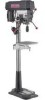
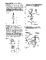
_[wr_,1 =t_'llKl[e_ To prevent personal injury, always disconnect plug from the power source when making any adjustment. SPINDLE I QUILL (FIG. N) Rotate the feed handles counterclockwiseto lower spindleto its lowest position. Hand supportthe spindlesecurely and move it back and forth around the axis. If there is too much play, do the following: 1. Loosen the lock nut (1). 2. Turn the screw (2) clockwiseto eliminate the play, but without obstructingthe upward movement of the spindle. (A little play in the spindle is normal.) 3. Tighten the lock nut (1). Fig. N QUILL RETURN SPRING (FIG. O) The quill return spring may need adjustment ifthe tension cause the quillto return too rapidly or too slowly. 1. Lowerthe table for additionalclearance. 2. Place a screwdriver in the lower front notch (1) of the springcap (2). Hold it in place while loosening and removingonly the outer jam nut (3). 3. With the screwdriverstillengaged in the notch, loosen the inner nut (4) just until the notch(5) disengages from the boss (6) on the drill press head. CAUTION: DO NOT REMOVE THIS INNER NUT, because the springwill forcibly unwind. 4. Carefully turn the spring cap (2) counterclockwise with the screwdriver, engaging the next notch. 5. Lower the quill to the lowest position by rotating the feed handle in a counterclockwise direction while holding the spring cap (2) in position. 6. If the quill moves up and down as easily as you desire, tighten the standard nut (4) with the adjustable wrench. If too loose, repeat steps 2 through 5 to tighten. If too tight, reverse steps 4 and 5. DO NOT OVERTIGHTEN and restrict quill movement. 7. Replace the jam nut (3) and tighten against the standard nut (4) to prevent the standard nut from reversing. Fig. O 2 To avoid injury from an accidental start, ALWAYS make sure the switch is in the "OFF" position, the switch key is removed, and the plug is not connected to the power source outlet before making belt adjustments. BELT TENSION (FIG. P) Make sure pulleys are aligned properly as shown in Figure R on page 15. 1. To unlock the belt tension, turn the belt tension lock knobs (1) on each side of the drill press head counterclockwise. 2. Tighten the belts by turning the belt tension handle (2) clockwise. 3. Loosenthe belts by turning the belt tensin handle (2) counterclockwise.Set belts on pulley steps for desired speed. 4. Lock the belt tension lock knobs (1) by turning clockwise. NOTE: Belt tension is correct if the belt deflects approximately 1/2 inch when pressed at its center. Fig. P 14
-
 1
1 -
2
-
3
-
4
-
5
-
6
-
7
-
8
-
 9
9 -
 10
10 -
 11
11 -
 12
12 -
 13
13 -
 14
14 -
 15
15 -
 16
16 -
 17
17 -
 18
18 -
 19
19 -
20
-
21
-
22
-
23
-
24
-
25
-
26
-
27
-
28
-
29
-
30
-
31
-
32
-
33
-
34
-
35
-
36
-
37
-
38
-
39
-
40
-
41
-
42
-
43
-
44
-
45
-
46
-
47
-
48
 |
 |
