Cub Cadet PRO Z 972S KW Operation Manual - Page 11
Notes
 |
View all Cub Cadet PRO Z 972S KW manuals
Add to My Manuals
Save this manual to your list of manuals |
Page 11 highlights
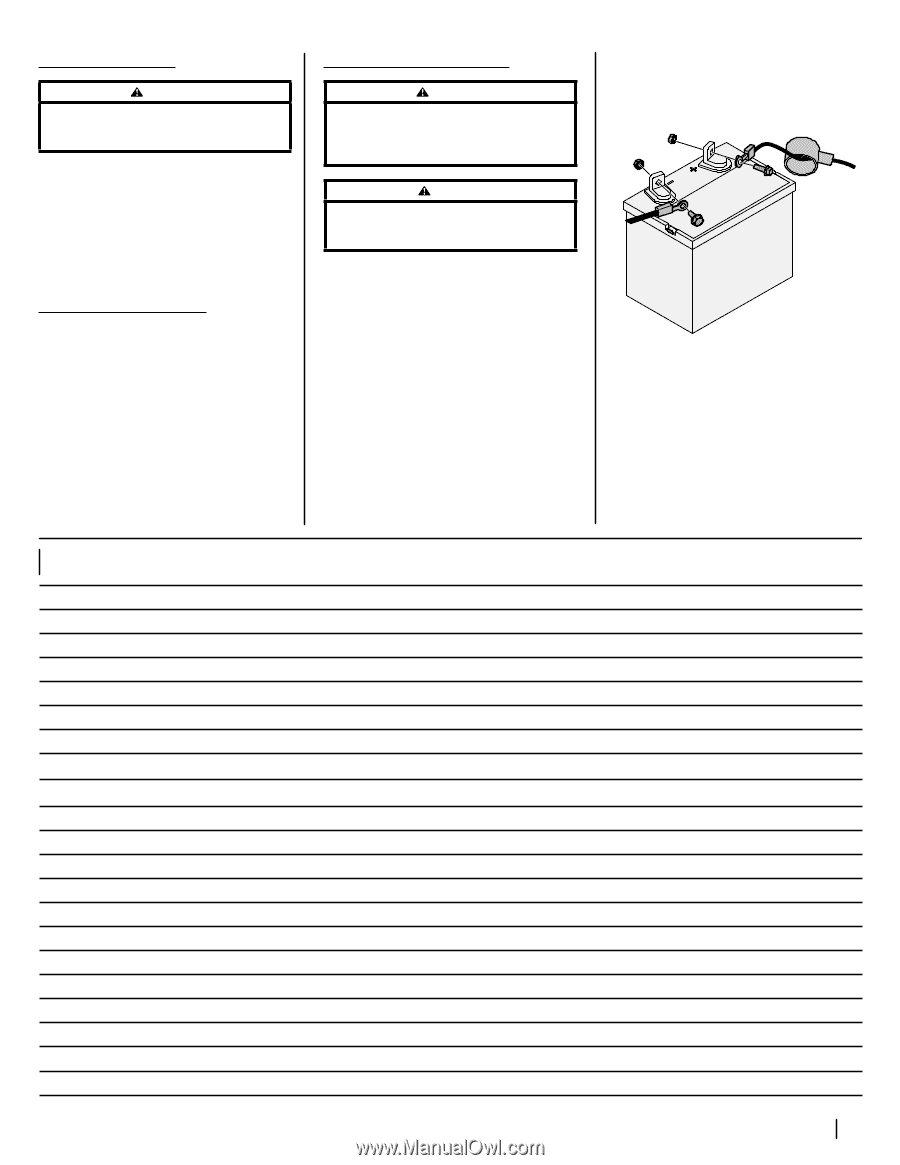
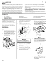
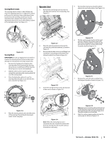
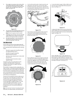
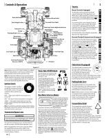
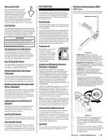
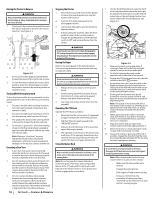
Checking Tire Pressure WARNING Maximum tire pressure under any circumstances is 12 psi on rear tires and 25 psi on front tires. Equal tire pressure should be maintained at all times. Inflation Pressure Rear Tires - 10-12 psi max Front Tires - 20-25 psi max The tires on your tractor may be over-inflated for shipping purposes. Reduce the tire pressure before operating the tractor. Recommended operating tire pressure is 10-12 psi on rear tires and 20-25 psi on front tires. Lubrication & Grease Points Before operating the tractor, refer to the Product Care section of this manual to check the lubrication and grease points. Grease and lubricate if necessary. Connecting the Battery Cables WARNING California PROPOSITION 65 Battery posts, terminals, and related accessories contain lead and lead compounds, chemicals known to the State of California to cause cancer and reproductive harm. Wash hands after handling. CAUTION When attaching battery cables, always connect the POSITIVE (Red) wire to its terminal first, followed by the NEGATIVE (Black) wire. For shipping reasons, both battery cables on your equipment may have been left disconnected from the terminals at the factory. To connect the battery cables, proceed as follows: 1. Using the lever on the back of the seat frame, lift up on the lever and tilt the seat forward locking it in place with the seat prop. Remove the bolts and hex nuts from the manual bag. Note: The positive battery terminal is marked POS. (+) (a). The negative battery terminal is marked NEG. (-) (b). Note: If the positive battery cable (c) is already attached, skip ahead to step 4. Notes 2. Remove the red boot (d), if present, from the positive battery terminal (a) and attach the red cable (c) to the positive battery terminal (a) with the bolt (e) and hex nut (f). See Figure 2-19. (f) (a) (c) (d) (f) (b) (e) (e) (g) Figure 2-20 3. Position the red boot (d) over the positive battery terminal (a) to insulate it and help protect it from corrosion. 4. Attach the black cable (g) to the negative battery terminal (b) with the bolt (e) and hex nut (f). See Figure 2-20. Note: If the battery is put into service after the date shown on top/side of battery, charge the battery prior to operating the machine. Section 2 - Assembly & Set-Up 11
-
 1
1 -
2
-
3
-
4
-
5
-
 6
6 -
 7
7 -
 8
8 -
 9
9 -
 10
10 -
 11
11 -
 12
12 -
 13
13 -
 14
14 -
 15
15 -
 16
16 -
17
-
18
-
19
-
20
-
21
-
22
-
23
-
24
-
25
-
26
-
27
-
28
-
29
-
30
-
31
-
32
 |
 |