Cub Cadet PRO Z 972S KW Operation Manual - Page 8
Assembly & Set-Up - review
 |
View all Cub Cadet PRO Z 972S KW manuals
Add to My Manuals
Save this manual to your list of manuals |
Page 8 highlights
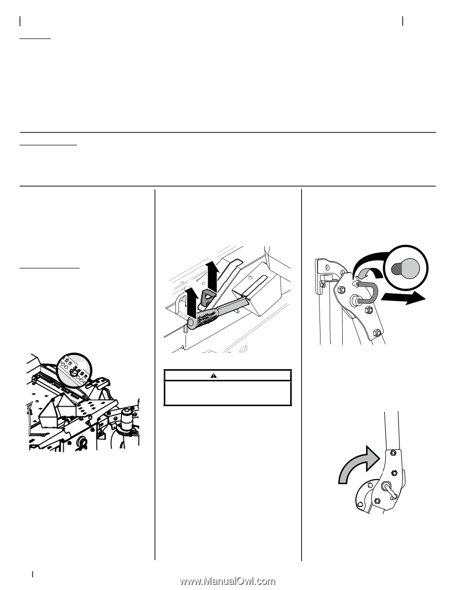
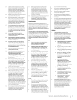
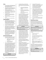
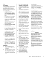
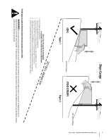
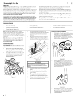
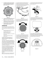
Assembly & Set-Up Thank You Thank you for purchasing this product. It was carefully engineered to provide excellent performance when properly operated and maintained. Please read this entire manual prior to operating the equipment. It instructs you how to safely and easily set up, operate and maintain your machine. Please be sure that you, and any other persons who will operate the machine, carefully follow the recommended safety practices at all times. Failure to do so could result in personal injury or property damage. All information in this manual is relative to the most recent product information available at the time. Review this manual frequently to familiarize yourself with the machine, its features and operation. Please be aware that this Operator's Manual may cover a range of product specifications for various models. Characteristics and features discussed and/or illustrated in this manual may not be applicable to Contents of Carton 2 all models. We reserve the right to change product specifications, designs and equipment without notice and without incurring obligation. If applicable, the power testing information used to establish the power rating of the engine equipped on this machine can be found at www.opei.org or the engine manufacturer's web site. If you have any problems or questions concerning the machine, phone your local authorized service dealer or contact us directly. We want to ensure your complete satisfaction at all times. Throughout this manual, all references to right and left side of the machine are observed from the operating position. • Zero-Turn Tractor (1) • Seat Mounting Hardware (1) • Engine Operator's Manual (1) Note: This Operator's Manual covers several models. Tractor features may vary by model. Not all features in this manual are applicable to all tractor models and the tractor depicted may differ from yours. Note: All references in this manual to the left or right side and front or back of the machine are from the operating position only. Exceptions, if any, will be specified. Tractor Preparation TOOLS NEEDED: Safety glasses, leather gloves, wire cutters. 1. Remove the upper crating material from the shipping pallet, and cut any bands or tie straps securing the tractor to the pallet. 2. Use the deck lift pedal (a) to raise the deck to its highest position and secure in place with the clevis pin (b) attached to the tractor. See Figure 2-1. • Steering Wheel (1) • Battery Installation Hardware (1) • Seat Tilt Knob Assembly & Hardware Pack (1) • Tractor Operator's Manual (1) 3. The two hydrostatic transmissions are equipped with a bypass valve that will allow you to manually move the tractor short distances. 4. Engage the transmission bypass valves by pulling the bypass lever (a) outward then upward and all the way back. See Figure 2-2. (a) (b) Roll Over Protective System (ROPS) 1. Pull slightly up on the upper ROPS to relieve any tension on the locking pin (a) and rotate the locking pin (a) from the LOCKED (b) position into the ADJUSTMENT (c) position. See Figure 2-3. Repeat the procedure for the locking pin on the opposite side. (c) (b) (a) (b) (a) Figure 2-1 Figure 2-2 WARNING Do not tow the tractor, even with the bypass valves engaged. Serious transmission damage will result from doing so. 5. Carefully roll the tractor off the shipping pallet. 6. To release the bypass lever (a), push the lever forward. 7. To engage the parking brake, pull back completely on the parking brake lever (b). 8. Cut any wire ties holding the chute deflector up and discard any packing material. Figure 2-3 2. When both locking pins are secured in the ADJUSTMENT position, slowly lift and rotate the upper ROPS from the TRANSPORT (a) position, past the TRANSPORT WITH BAGGER (b) position and into the OPERATION (c) position. See Figure 2-4. (b) (c) (a) Figure 2-4 3. Rotate both locking pins into the LOCKED position. Move the upper ROPS slightly until the locking pins are fully engaged in the LOCKED position. 8
-
 1
1 -
2
-
 3
3 -
 4
4 -
 5
5 -
 6
6 -
 7
7 -
 8
8 -
 9
9 -
 10
10 -
 11
11 -
 12
12 -
 13
13 -
14
-
15
-
16
-
17
-
18
-
19
-
20
-
21
-
22
-
23
-
24
-
25
-
26
-
27
-
28
-
29
-
30
-
31
-
32
 |
 |